Transcription of Downsizing Resistance Welding - microJoining
1 Downsizing in the World of Resistance WeldingDavid W. Steinmeier - microJoining Solutions Copyright 1998 All Rights Reserved, May 13, 19981 General Comparisons Between Large, Small, and Micro-Scale Resistance Spot WeldingLarge Scale Resistance Spot WeldingWhen most Welding engineers think about spot Welding ,the typical picture that immediately comes to mind is alarge robotic arm swinging around in space with streamsof sparks flying everywhere as a car body is assembledor large panels of sheet metal are joined together tomake a refrigerator or an industrial piece of machinery Galvanized steel sheets ranging in thicknessfrom .016 inches ( mm) to .125 inches ( mm)are routinely joined using Resistance spot extensive use of standard thickness sheet metal panels, made from common, well characterized steelalloys, and plated with standardized zinc coatings, makes life more manageable for our large scalewelding engineer.
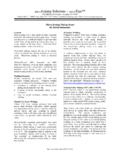
2 Materials standardization in fact has permitted the creation of spot Welding tables thatdefine what spot Welding technology should be used, exactly how much weld current, time, and forceare needed, along with what electrode alloy and tip shape are requiredto make a good spot Scale Resistance Spot Welding - Life just became complicatedNow picture our Welding engineer being faced with the task ofresistance Welding one end of a .015 inch ( mm) diameternickel wire onto a tin plated brass alloy terminal that is .025inches ( mm) thick by .187 inches wide ( mm) inside ofa modern automotive ignition module Problems likeautomatically holding and placing the wire over the terminal on arepeatable basis become significant. The plastic housing, with itsembedded terminals, must be designed to provide access for thewelding electrodes. After solving the parts handling andelectrode access problems, our Welding engineer finds that thereare no Welding tables that define what type of spot weldingtechnology should used for his application, let alone any startingset of process 1 Photo of car body being weldedby robotic Resistance spot Welding .
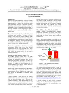
3 (Use AWS stock photo)NickelWireUpperElectrodeTerminalLo werElectrodeFig. 2 Opposed Welding of nickelwire to tin plated brass terminal. Downsizing in the World of Resistance WeldingDavid W. Steinmeier - microJoining Solutions Copyright 1998 All Rights Reserved, May 13, 19982To complicate matters, the opposite end of the nickel wire mustbe automatically positioned and parallel gap welded to a .020inch ( mm) thick by .15 inches ( mm) square nickel padthat had been fused to the electronic control printed circuit board Once again, our Welding engineer has no Welding tablefor selecting the appropriate spot Welding technology and startingprocess this point, it is becoming apparent to our Welding engineer thatthere is something very different between large scale and smallscale Resistance spot Scale Resistance Spot Welding - Life just became verycomplicatedOur Welding engineer decides to escape his small scale Resistance Welding problems by changing medical products field is growing so he takes a position with a company that is developing a newimplantable bio-sensor.
4 His first task is to develop a Resistance Welding process for joining a .002 inch(50 micron) diameter platinum wire to a .010 inch ( mm) square by .001 inch (25 micron) thick goldplated copper pad on a flexible printed circuit board. Like the small scale Resistance Welding problem,there are no Welding tables to help our Welding engineer select the appropriate Welding technology andprovide him with starting process Differences Become More ApparentThe size of the large scale Resistance spot Welding application market is easily an order of magnitudegreater than small and Micro-Scale Resistance Welding applications. Large scale Resistance spot weldingis well over 100 years old and represents a mature joining process. There has been ample time formaterials to become standardized as to alloy types, plating, and thickness. These factors have driven thecreation of Welding tables that clearly define the large scale Resistance spot Welding and Micro-Scale Resistance spot Welding on the other hand is being fueled by the explosion tomake everything smaller, from automotive electronics, to telecommunications components and medicalproducts.
5 The only thing that these applications have in common is their lack of commonality. Evenwithin a single applications sector such as automotive electronics, the alloys, plating, part geometry, andthermal loading are vastly different from application to application, making the creation of standardizedwelding tables almost article provides the Welding engineer familiar with large scale Resistance spot Welding with somebasic knowledge about materials, weld energy controls, weld force controls, electrodes, and partsfixtures to help ensure his joining success as he downsizes into the realm of small and Micro-Scalespot 3 Parallel gap Welding ofnickel wire to nickel pad that is fusedto a printed circuit board substrate. Downsizing in the World of Resistance WeldingDavid W. Steinmeier - microJoining Solutions Copyright 1998 All Rights Reserved, May 13, 19983 Part MaterialsAlloys, Thickness Range, and Applications - Large Scale Spot WeldingThe majority of large scale Resistance spot Welding applications use parts fabricated from galvanized lowcarbon 1010 and 1100 cold roll steel along with 304, 316, and 400 series low carbon stainless steels,ranging in thickness from.
6 016 inches ( mm) to .062 inches ( mm). The effects of spot weldingon these common materials is well known and documented. The American Welding Society (AWS),800-443-9353, Resistance Welding Manufacturers Association (RWMA), telephone 215-564-3484, andspot Welding suppliers like Contacts Metals Welding (CMW), telephone 317-634-8884, all publish spotwelding parameter tables for large scale Resistance spot Welding of the most common steel alloys 1 provides a list of the most common materials, thickness range, and applications joined by largescale spot 1 - Large Scale Spot WeldingTypicalMaterialsPlatingTypesCommo n ApplicationsThickness Range: .016 to .062 inches ( to mm)1010 & 1100 Cold Roll SteelNone, Tin, ZincAppliances, auto body panels and frames, boxes andenclosures, Steel furniture304, 216, 410 Stainless SteelNoneBoxes and enclosures, steel furniture, supporting bracketsand structuresAlloys, Thickness Range, and Applications - Small Scale Spot WeldingIn addition to using many of the same stainless alloys used by large scale spot Welding , small scale spotwelding uses a wide variety of brass, copper, inconel, nichrome, and nickel based alloys.
7 Difficult tojoin materials such as molybdenum and tungsten are also used in making high intensity vapor arc lampsfor automotive headlamp, street, and security lighting. Typical plating materials include tin/lead solderover brass and copper, pure tin, nickel, silver, and gold. There are no detailed published Resistance spotwelding guides or tables for joining these materials since the part size, geometry, plating type andthickness vary substantially from application to application. Table 2 provides a list of the most commonmaterials, thickness range, plating types, and applications joined by small scale spot Welding . Downsizing in the World of Resistance WeldingDavid W. Steinmeier - microJoining Solutions Copyright 1998 All Rights Reserved, May 13, 19984 Table 2 - Small Scale Spot WeldingTypicalMaterialsPlatingTypesCommo n ApplicationsThickness Range: .005 to .020 inches ( to mm)Brass AlloysNone, Tin/lead, Tin,Nickel, SilverElectronic terminals, relay supportsCopperNone, Tin/lead, Tin,Nickel, SilverElectronic terminals, relay supportsCopper AlloysNone, Tin/lead, Tin,Nickel, SilverElectronic Terminals, relay supports, bi-metal componentsInconelNoneAircraft componentsMolybdenumNoneAuto headlamps, street lamps, medical lampsNichromeNoneBi-metal sensors, detonating devicesNickelNoneRechargeable battery packs, electronic circuits, bi-metalsensorsSilver AlloysNoneRelay contactsStainless SteelNoneMedical catheters, small surgical instruments and devicesTungstenNoneAuto headlamps, street lamps, medical lampsAlloys, Thickness Range, and Applications - Micro-Scale Spot WeldingThe world of Micro-Scale spot Welding begins at a part thickness of.
8 005 inch ( mm) and goesdown to about .0005 inches (12 microns). The most common materials found in Micro-Scale spotwelding are 304L and 316L stainless steel, copper wire, nickel, platinum, and titanium. Table 3provides a list of the most common materials, thickness range, plating types, and applications joined byMicro-Scale spot 3 - Mciro-scale Spot WeldingTypicalMaterialsPlatingTypesCommo n ApplicationsThickness Range: .0005 to .0050 inches ( um to )CopperNone, Tin/lead,Tin, Nickel, SilverElectronic circuit connectionsGoldNoneElectronic circuit connectionsNickelNoneElectronic circuit connectionsNitinolNoneMedical guide wires and stentsPlatinumNoneElectronic circuit connections and medical device sensorsStainless SteelNoneMedical catheters, guide wire, micro- cutting instruments anddevices Downsizing in the World of Resistance WeldingDavid W. Steinmeier - microJoining Solutions Copyright 1998 All Rights Reserved, May 13, 19985 Part Geometry and Thermal LoadingPart shape or geometry on small and Micro-Scale size parts can make or break the possibility ofachieving a successful spot weld through the creation of large thermal imbalances, particularly ifthermally mismatched parts are being welded together.
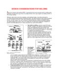
9 For example, spot Welding the .015 inch ( ) diameter nickel wire to the .025 inch ( mm) thick brass terminal described earlier ispotentially a big problem because of the large heat sinking capability of the brass terminal in comparisonto the limited heat absorption capability of the small nickel compensate, the knowledgeable weldingengineer will work with the terminal designer tocreate a thermal island in the brass task can be accomplished in several ways. Ahole can be placed in the terminal, slowing downthe loss of heat from the Welding area to the largerthermal mass portion of the terminal. A projectioncan be stamped into the brass that has a smallcontact area and smaller cross sectional thicknesscompared to the larger area and cross section ofthe brass terminal In summary, theprimary goal of part design for weldability is touse geometry to effect a heat balance betweenthermally disparate same techniques of creating thermal islands also apply to large scale Resistance spot , the absolute size of these thermal islands and their fabrication tolerances exceed small andMicro-Scale applications by a factor of ten times or FinishAs the size of the parts to be Resistance spot welded decreases, the surface finish quality of each parttakes on more importance.
10 For example, squib or detonating wire used in making automotive airbag oraircraft canopy and ejection seat detonators can range in size from .0005 inches ( microns) indiameter to .0020 inches (50 microns) in diameter and are made from platinum iridium, platinum-tungsten, nichrome, or stainless alloys. One side of the squib wire is typically welded to the top of aconnecting pin made of nickel-iron or stainless steel while the other end is welded to a header surfacemade from a stainless steel alloy. In the case of the .0005 inch ( microns) diameter wire, the matingsurface finish peak-to-peak variations should not exceed .00005 inches ( microns) or the weldingprocess will not be repeatable. Variations in peak-to-peak surface finish approaching .00025 inches ( ) can actually cut the wire during Welding and definitely create an inconsistent electrical contactresistance which in turn translates into unexplained blow-outs and inconsistent 4 Creation of a thermal island using ahole and using a projection.