Transcription of DRAFT - ladpw.org
1 Updated Structure Design Manual, April 1982 Page I-1 DRAFT Revise January 10, 2008 Section I - Reinforced Concrete Pipe DRAFT Section I Design of Reinforced Concrete Pipe I-1 Standard Installations The methods to be used for design of reinforced concrete pipe are the Indirect Design and Direct Design methods. The D-Load Tables that appear on 1982 Ver. Manual pages S-38 through S-64 are based on conservative principles using Marston-Spangler formulas developed in the 1930s. These tables may be used for reference and design should be based on the methods that appear in this update.
2 Indirect design method, using D-Loads, is a widely used empirical method for selecting and specifying pipes. The specified D-Load for a pipe is the minimum test load where cracks no more than inch in width are generated in a three-edge bearing test. D-Load for pipes is calculated through employing an empirical procedure that relates the three-edge bearing test loads to the actual required performance of the pipe in the installed field condition. The variables in the D-Load procedure are: total vertical loads acting on the pipe, installation conditions, pipe diameter, and depth of cover.
3 Pipes with inch cracks do not automatically indicate the structural integrity of the pipe is compromised. However, it is prudent to verify the performance of these pipes. Direct design method follows the principles of strength of material and reinforced concrete design. The designer needs to determine all the internal forces and stresses and perform the design in accordance to the design formulas prescribe in the subsequence Subsections. Due to the complexity of the initial structure analysis and the cumbersome design procedure that follows, Direct design methods should only be considered when the pipe is greater than 72 inches and the required D-Load is greater than 2000.
4 In general, embankment condition with Standard Installation Type 3 should be assumed for the design of pipes. It is preferred that pipes less than 72 inches in diameter be designed using Indirect method. For larger diameter pipe, Direct design might be more appropriate. The Indirect and Direct design methods prescribed within this Section, are based on Section 16, Soil-Reinforced Concrete Structure Interaction Systems, of Caltrans Bridge Design Specifications, April 2000 (1996 AASHTO with Interims and Revisions by Caltrans).
5 Updated Structure Design Manual, April 1982 Page I-2 DRAFT Revise January 10, 2008 Section I - Reinforced Concrete Pipe Standard Pipe Installations are presented in Los Angeles County Department of Public Works, Standard Plan 3080-3; these figures define soil areas and critical dimensions. Soil types, minimum compaction requirements, and minimum bedding thicknesses for Standard Pipe Installation. I-2 Design Design shall conform to applicable sections of this manual except as provided otherwise in this Section.
6 For design loads, see Subsection I-3; for Standard Installations, see Subsection I-1. Live loads WL, Fluid weight Wf shall be included as part of the total load WT, and shall be distributed through the earth cover as specified in Subsection Other methods for determining total load and pressure distribution may be used, if they are based on successful design practices or tests that reflect the appropriate design conditions. I-3 Loads Earth Loads and Pressure Distribution Earth Loads and Pressure Distribution The effects of soil-structure interaction shall be taken into account and shall be based on the design earth cover, side fill compaction, and bedding characteristics of the pipe soil installations.
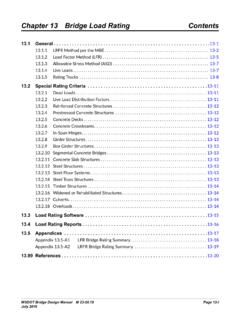
7 Updated Structure Design Manual, April 1982 Page I-3 DRAFT Revise January 10, 2008 Section I - Reinforced Concrete Pipe Figure I-1 Table I-1 InstallationType VAF HAF Al A2 A3 A4 A5 A6 a b c e f u v 1 2 3 Notes: 1. VAF and HAF are vertical and horizontal arching factors.
8 These coefficients represent nondimensional total vertical and horizontal loads on the pipe, respectively. The actual total vertical and horizontal loads are (VAF) X (PL) and (HAF) X (PL), respectively, where PL is the prism load. 2. Coefficients Al through A6 represent the integration of nondimensional vertical and horizontal components of soil pressure under the indicated portions of the component pressure diagrams ( , the area under the component pressure diagrams). The pressures are assumed to vary either parabolically or linearly, as shown with the nondimensional magnitudes at governing points represented by h1.
9 H2, uh1, vh1, a, and b. Nondimensional horizontal and vertical dimensions of component pressure regions are defined by c, d, e, uc, vd, and f coefficients. 3. d is calculated as ( c-e) h1 is calculated as ( )/(c) (I + u) h2 is calculated as ( )/[(d) (1 + v) + (2e)]. Updated Structure Design Manual, April 1982 Page I-4 DRAFT Revise January 10, 2008 Section I - Reinforced Concrete Pipe Standard Installations For the Standard Installations given in Subsection I-2, the earth load, WE, may be determined by multiplying the prism load (weight of the column of earth) over the pipes outside diameter by the soil-structure interaction factor, Fe, for the specified installation type.
10 WE= Fe w Bc H. w= unit weight of soil, lbs per cubic foot. Bc= out-to-out horizontal span of pipe, or box, foot. H = height of fill above top of pipe, foot. Standard Installations for both embankments and trenches shall be designed for positive projection, embankment loading conditions where Fe =VAF given, in Figure I-1 and Table I-1, for each type of Standard Installation. For Standard Installations, the earth pressure distribution shall be the Heger pressure distribution shown in Figure I-1 for each type of Standard Installation.