Transcription of Drawing an Approximate Representation of an …
1 105 Webster St. Hanover Massachusetts 02339 Tel. 781 878 1512 Fax 781 878 6708 Drawing an Approximate Representation of an involute Spur Gear Tooth Project Description Create a solid model and a working Drawing of the 24 pitch gears specified below. It is only necessary to create an approximation of the gear tooth form. These models can be used in both virtual and actual mechanical assemblies that you design an build using the GEARS- IDS kit. 60 Tooth Gear Specifications 36 Tooth Gear Specifications Pitch 24. Teeth 60 Pitch 24. Bore 7/16 Hex Teeth 36.
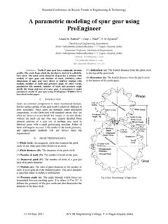
2 Material Delrin Bore 7/16 Hex Set Screw #10-24 (not shown) Material Delrin Hub Dia. Set Screw #10-24 (not shown). Face Width Hub Dia.. PA 200 Face Width . PA 200. Note: !0-24 Set Screw to intersect the middle of the flat on the hex bore. Note: !0-24 Set Screw to intersect the middle of the flat on the hex bore. The figure on the left is an example of a working Drawing of the 60 tooth gear specified above. This example also includes a pictorial Representation of the gear. drawings and specifications like these are prepared for a manufacturer so that he/she might prepare a production quote.
3 The only additional information required to estimate the cost of producing this gear would be the quantity required. Fig. 1 Working Drawing of a Spur Gear 1. 105 Webster St. Hanover Massachusetts 02339 Tel. 781 878 1512 Fax 781 878 6708 Procedure for Drawing an Approximation of a Spur Gear The following procedure can be used to create gear models using CAD workstations. This method will produce an approximation of the gear tooth form well suited for assemblies and animations. It is neither necessary nor efficient to take the time to draw an exact involute tooth form for the purpose of creating working drawings and models.
4 Note: Refer to the Spur Gear Definitions and Formulas table at the end of this document for explanations of the formulas listed below. In this example we will draw the 36 tooth, 24 pitch spur gear. Using this example you will be able to draw a spur gear having any number of teeth and pitch. Begin by laying out the Pitch, Root and Outside circles of the 36 tooth gear. 1. Calculate and draw the Pitch Circle. The Diameter of the Pitch Circle is calculated below;. N 36. a. D = D= = ". P 24. 2. Calculate and draw the Root Circle. The formula to determine the Root Circle Diameter is given below.
5 N 2 36 2 34. a. RD = = RD = = RD = = . P 24 24. 3. Calculate and draw the Outside Circle. The formula to determine the Outside Circle Diameter is given below;. N +2 36 + 2 38. a. OD = = OD = = OD = = . P 24 24. 4. Draw a vertical center line (AB. ) from the center of the circles to a point outside the circles. 5. Calculate and layout the Circular Thickness angle to the left (CC W) of the vertical center line. a. Calculate the angular measurement for the circular thickness using the following formula For this example: 360 o = Circular Thickness Angle No# Teeth 360 o = 5 o Fig.
6 2 Initial Layout and Circular Thickness Angle 36. Note: In the equation above, it is necessary to multiply by (or divide by 2) since there are always an equal number of teeth and spaces in each gear! 2. 105 Webster St. Hanover Massachusetts 02339 Tel. 781 878 1512 Fax 781 878 6708 6. Draw the Pressure Line. The pressure line is drawn through the pitch point at an angle of 20 degrees from a line tangent to the top of the pitch circle. The Pressure Line 7. Create a line that bisects the circular thickness angle. This line should intersect or extend beyond the outside circle as shown in figure 3 below.
7 The Circular Thickness Angle Bisector 3. 105 Webster St. Hanover Massachusetts 02339 Tel. 781 878 1512 Fax 781 878 6708 at the center of the circles, draw the Base Circle tangent to the 20 degree pressure line. Note that in this 36 tooth, 24 pitch gear example, the base circle will have nearly the same diameter as the root circle. This will not be the case with spur gears having different numbers of teeth, or different pitch. Therefore it is necessary to follow these instructions closely in order to establish accurate gear tooth geometry. Create the Base Circle 9.
8 Locate the Tooth Form Circle by Drawing circle (A) whose radius is 1/8 of the Pitch Diameter and whose center is at the Pitch Point. Radius = PD/8. Radius = Radius = . Circle A. Fig. 6 Tooth form locator 4. 105 Webster St. Hanover Massachusetts 02339 Tel. 781 878 1512 Fax 781 878 6708 10. Draw another circle (B) of the same radius whose center is at the intersection of circle A and the Base Circle. This circle will form the top right curve of the gear tooth B. Root Circle Point at which circle A intersects the base circle Base Circle Fig. 7 Locate the Tooth Form Circle A and trim away all of circle B, except the tooth form which is arc PT beginning at the pitch point and intersecting the outside circle.
9 Erase the Base circle. Create the Tooth Form Root Circle 5. 105 Webster St. Hanover Massachusetts 02339 Tel. 781 878 1512 Fax 781 878 6708 you can see in this example, the tooth form is generated from the Pitch Point. Continue developing the gear tooth form by tracing over the vertical centerline and trimming away the outside circle. After creating the tooth form, erase all lines EXCEPT the circular thickness bisector, the tooth from lines and the base circle. See figure 8and 9 below. Fig. 9 Trace the Tooth Form Fig. 10 Tooth Form 6. 105 Webster St.
10 Hanover Massachusetts 02339 Tel. 781 878 1512 Fax 781 878 6708 the tooth form lines about the circular thickness bisector. Circular Thickness Bisector Mirror the Tooth Form the circular thickness bisector and array the completed tooth form about the base circle. Array the Tooth Form 105 Webster St. Hanover Massachusetts 02339 Tel. 781 878 1512 Fax 781 878 6708 7. 15. Trim the base circle line under each tooth to create a single closed form. Trim the Tooth Form 16. Extrude the gear a distance of . This dimension is given in the specifications on the first page of this text.