Transcription of Drop tap and Home Run Designing - ATV Research Inc.
1 drop Tap and home Run Designing Copyright ATV Research Inc. 1999. After thousands of consultations on the subject of MATV and SMATV there is one area that stands out as causing a major percentage of the confusion - and that's the hassles associated with the distribution of cable and off-the-air TV signals throughout large complexes ..whether it be a motel, hotel, hospital, nursing home , apartment house or just a good sized residence. Some would say there are only two systems to be considered, drop TAP or home RUN but In reality, there is a third system, that being a hybrid combination of these two systems.
2 From this starting point, we shall proceed to define the elementary principles that need to be understood to successfully design your own system. We'll start with the drop tap system since it is the most com- monly used procedure in larger systems (motels, hotels, hospitals and the like). Also, it is the system that causes the most worry with newcomers to the area of master distribution. All rf tv systems specify cables that are nominally 75 ohms impedance. The most popular flexible coax cables being RG-59U and RG-6U for the smaller systems with RG-11U sometimes being specified on longer runs or in bigger for the main trunk runs.
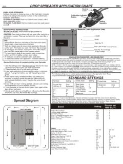
3 It is absolutely imperative to not mix 75 ohm type cables with other impedances ( , 52 ohm). You can however, have a mix of 75 ohm type cables such as RG-6U and RG-11U or is completely acceptable. All things considered, most satellite dealers and cable companies use RG-6U almost exclusively. It's the best compromise for cost and performance. Before starting, it is suggested you have a cable attenuation chart for the brand of cable you will be using as well as a loss chart for the drop taps of your Without this information you can use the generic charts shown in fig. 1 with reasonable accuracy. Before any calculations can be made, it is necessary to know the headend output level.
4 It may be any- thing from 20db to 60db. Typically we find that most commercial systems run about 50db and most home systems in the 20-30db range. Once you know the type of cable and are familiar with the loss per hundred feet at the lowest and the highest channels you can proceed to calculate the first drop tap value. Since most tap manufacturers don't offer tap values greater than 30db, it is quite conceivable that the first TV will get a somewhat stronger than necessary is not considered a serious problem. The term tilt is synonymous with cable distribution and refers to the fact that high frequency channels attenuate faster in the coaxial trunk line than the low frequency channels.
5 It's very important to watch the amount of tilt in your system, otherwise it could completely destroy the performance of some or all of the channels. Therefore, assuming anything other than the smaller systems, it is important to calcu- late db levels at both ends of the range. A good rule-of-thumb: any time a trunk line is more than about 200 feet, tilt becomes a factor that should not be ignored. Let's assume we are Designing a mid-sized complex of 30 drops, all in a single line. We'll use RG-6U. cable and the system will be a 550 Mhz cable system with channel 78 being the highest channel. The output from the headend combiner is 40db.
6 The first drop tap is right in the headend room. Obviously, a 30db tap will be ideal. Referring to the manufacturer's drop tap loss chart you will note that the average thru-loss is about , thus the signal exiting the first drop tap is now about Let's continue approximately 100 feet to our second drop . Again, referring to the cable chart, it is clear that the loss at ch. 2 is and at ch. 78 it is That means we now have about 38db at ch. 2. and at ch. 78. A 30db tap will still work at this point since our goal is to maintain a positive db level above zero. Already you can begin to see what tilt in a system can do.
7 To quickly illustrate the effects of cable tile lets assume the next tape be be 200 feet down the line. Once again, thru-loss on the tap is figured at and cable losses calculated from the chart in fig. 1. The resulting values now are approximately at ch. 2 and at ch. 78. Tilt is now at The tap value will now need to be 20db in order to meet good engineering practices ..that is to say, keeping our levels above 0 at the highest channel. With slightly over 8db of tilt now showing in our system we much correct immediately with tilt compensation or pay the serious concequences of a degradated signal beyond this point.
8 We generally like to use an active compensation amp because we can offset the losses thus far and provide a good signal level for the balance of the run. Using these principles, it is clear to see that Designing a drop tap system is really quite easy, although the calculation can be a little time-consuming. In reality, however, time spent on paper with the calculator will result in a much shorter time on the job site. From this little example it's easy to see why shorter runs with less drop taps on any one leg are more desirable and easier to calculate. Longer runs almost always require a certain degree of tilt compensa- tion and intermediate amplification.
9 In reality most of the large complexes use a splitter near the headend and/or part way down the trunk line to feed different wings, floors and hallways. Although they are basically drop tap systems, they are more like the hybrid combination of drop tap and home run systems mentioned earlier. Here's some simple rules that will make drop tap Designing easier and more successful;. 1. Always calculate for lowest channel and highest channel losses 2. Know your cable per/hundred ft. losses 3. Know your drop tap characteristics, especially thru-losses . 4. Be sure to maintain + db levels at both the low and high channel limits 5.
10 Generally attempt to maintain levels between +2 and +10db (this will help in keeping stray leakage radiation to an absolute minimum and at the same time prevent excessive power from being unnecessarily sapped from the trunk line.). 6. ALWAYS terminate the last drop tap in a ghosting and other degradation problems can occur to the picture quality.). 9. Add tilt compensation (passive or a tilt-compensating amp) when levels get too low, or when tilt becomes intolerable. 10. Never use 6db drop taps until absolutely necessary. The thru-loses are too great. In a nutshell that's the information you need to go out and start Designing your own drop tap least the simpler ones.