Transcription of DSX Access Systems, Inc.
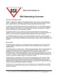
1 DSX Access Systems, Inc. 10731 Rockwall Road Dallas, Texas 75238 / 888-419-8353 / 8/2011 DSX Access Systems, Inc. DSX-1022 Typical Connections DSX-1022 Intelligent Controller Typical Connections SIDE A1K OHM CONTACTSNCNO1K OHM EXIT BUTTONSIDE BMOVNCNODPDT EXIT BUTTON1K OHM OHM CONTACTSMAGLOCKPANEL TAMPERE nclosed AC Power "ON" LED Must be wired in parallel with the AC transformer for UL 40VA Transformer must be within 25 feet of thePanel and plugged into a 115V AC non-switched duplex outlet. The transformer cannot be shared with any other UL certified installations, the battery must be UL listed such as the Powersonic PS-1270, the Interstate PC-1270 or SBS S-1272 rated at 12V, 7AH.
2 The charging circuit will recharge up to 2 of the above listed batteries within one 1022 panels must be Grounded forproper panel operation and transient voltage / 7 AHBattery-++ VOLTAGESIDE B PRE-ALARM SOUNDER+ VOLTAGESIDE A PRE-ALARM SOUNDERMOVMAGLOCKHID PROXDS-12 KEYPADLOCK POWER SOURCELOCK POWER SOURCE250V 3A BATTERY250V 1/2A AUX 5 VDC250V 1A AUX 12 VDC1A 250V OUTPUT A11A 250V OUTPUT A21A 250V OUTPUT B11A 250V OUTPUT B2485 IN485 OUTMASTER 485 IN59 TX+58 TX-57 RX+56 RX-55 TX+54 TX-53 RX+52 RX-51 TX+50 TX-49 RX+48 +GNDLOW ACHI ACDSX-1022 ControllerDSX Access Systems, Inc.(800)346-5288 Panel Status LED'sPower *Poll *Buffer *Download *Heartbeat *Addressing DipswitchSwitchValue123456781248163264 Master/SlaveAddressing:-Master Panel : Switch 8 ON, use switches 1-7 to set Location # (master panel is always devices 0 and 1)-Slave Panel : Switches 1 and 8 OFF, use switches 2-7 to set EVEN device # from 2 to 126*Low AC Indicator*High AC ,40VA ,40VA InputEarth GNDB attery +Battery -*AC ON Indicator*Low Battery IndicatorPanel to Panel RS-485485 INTX+TX-RX+RX-485 OUTTX+TX-RX+RX-PC to Master RS-485TX+TX-RX+RX-Master to Slave:Wire IN to IN, TX to RXSlave to Slave.
3 Wire OUT to IN, TX to TXMaster Loc 3 First SlaveSecond Slave1 ON2 ON3 OFF4 OFF5 OFF6 OFF7 OFF8 ON1 OFF2 ON3 OFF4 OFF5 OFF6 OFF7 OFF8 OFF1 OFF2 OFF3 ON4 OFF5 OFF6 OFF7 OFF8 OFFO utputs:SPDT, Form C contacts rated at 5A @ 30 VDC or 30 VAC With 1A rated fuse inline with Common :Open Collector output can sink 100mA. Starts pulsing at 1/3 Door Hold Open time and on solid when Input 7 is in alarm. Reader LED's:Open Collector outputs can sink 100mA when active LED 1 - Pulls low when Output 1 is "secure" LED 2 - Pulls low when Output 1 is "open" LED 3 - Pulses to indicate "keypad mode" or " Access denied"Reader Data Lines: D0-Wiegand Data 0 or Clock line (usually green wire) D1-Wiegand Data 1 or Data line (usually white wire Reader Voltage Outputs:5 VDC @.)
4 5A total / 12 VDC @ 1A totalInputs:-Can be wired for 2,3 or 4 state monitoring-Can use (parallel) or (series) contacts-Use 1K OHM resistor for 2 and 3 state monitoring-Use 180 and 820 OHM resistors for 4 state monitoring-Input 7 is Door Contact, Input 8 is Exit RequestREPLACE FUSES WITH SAME TYPE AND SPECIFICATION(LED On = Blown Fuse)*F3-Battery Fuse, 3A*F2-Aux 5V Fuse, .5A*F1-Aux 12V Fuse, 1 ALittlefuse 312003 Littlefuse 312001F4-Output A:1 Fuse, 1 ALittlefuse 312001F5-Output A:2 Fuse, 1 ALittlefuse 312001F6-Output B:1 Fuse, 1 ALittlefuse 312001F7-Output B:2 Fuse, 1 ALittlefuse 312001 Side A Outputs, Reader Port and InputsSide B Outputs, Reader Port and InputsOutput A:1 Output A:2 Reader Port ASide A InputsSide B InputsReader Port BOutput B:1 Output B:244 45 46 4740 41 42 4336 37 38 3932 33 34 3528 29 30 31272622 2324 2518 19 20 2114 15 16 1710 11 12 136 7 8 9 INPUTS AA5 A6 A7 A8 CINPUTS BB5 B6 B7 B8 CLED1 LED2 LED3D0D15 VGND12 VLED1 LED2 LED3D0D15 VGND12 VOUTPUT A1NC C NO PAOUTPUT A2NC C NO GNDOUTPUT B1NC C NO PAOUTPUT B2NC C NO GNDTo next Controller or from previous Controller.
5 See Quick Ref. Card or Hardware Installation Manual for Twisted Pairs22 AWG 4000 FT MAXEXHAUST FANTO 12V & GROUND OF READER PORTO utput Extender:Use the DSX-OX4 to provide 4 additional Form-C Output Relays, One Extender can connect to a DSX-1022 at the Master (485 IN) port of a SLAVE CONTROLLER. (Required Terminations include TX-RX, RX-TX & +12 VDC & GND).Reader Connection Definitions:Pre-Alarm connection is an open collector capable of -100mA DC current. Pre-Alarm normally connects to a sounder located near a controlled door to indicate a door has been held open too 1provides (-100mA) to the Reader Secure LED when "Secure".LED 2provides (-100mA) to the Reader Open LED when "Open".LED 3provides 2 (-100mA) pulses to the Reader Access Denied LED when there is an " Access Denied" 0provides a Data 0 or "Clock" signal to the 1provides a Data 1 or "Data" signal to the controller.
6 +5 VDC provides up to 5 VDC rated at 500mA to power aka GND provides the Reader with a Ground.+12 VDC provides 12 VDC rated at 1A to power : The +12 VDC connection also can be used to provide voltage to other components, such as the DSX Modem. This power supply is shared between the Side A and the Side B Reader LED Definitions:POLL Flashes at a Slave to indicate Comm. to Master is On to indicate panel is storing all history is On to indicate the panel is being programmed by the Flashes to indicate the panel is LED is On to indicate AC voltage is AC is On when the AC at panel is approx. 15V or BATTERY is On when battery voltage drops to approx. or LEDs are On to indicate the input is LEDs are On when the relay coil is Type:Output Relays Provide Form C, Dry Contact, SPDT, rated at 5A at 30 VDC or 30 VAC.
7 Contacts provided include NO, C, NC. Each Output Relay includes a 1A fuse inline with the Common Circuit Types:Type 0- Can monitor NO and/or NC switches, req. 1k Ohm EOL, no 1- Can monitor NC switches, req. 1k Ohm EOL, Sensor open = Alarm, Circuit short = 2- Can monitor NO switches, req. 1k Ohm EOL, Sensor short = Alarm, Circuit open = 3- Can monitor NC switches, req. 180 and 820 Ohm EOLs, Sensor open = Alarm, Circuit open = Trouble, Circuit short = 4- Can monitor NO switches, req. 180 and 820 Ohm EOLs, Sensor closed = Alarm, Circuit open = Trouble, Circuit short = Usage:If voltages higher than 50 volts are to be switched through the Output relay contact, the individual MOV's (V1&V2, V3&V4, V5&V6 or V7&V8) should be removed from the specific to PCRS-232To MasterRS-485To MasterDSX-LANDSX-MODEMDSX-MCI (RS-485)MASTER 485 IN49 RX+ to TX+ ofPC to Master RS-485of DSX-1022TX+TX-RX+RX-DSX-USB (RS-485)OROROR50 TX- to RX- of48 RX-to TX- of51 TX+ to RX+ of