Transcription of Dual Channel, High Speed Optocouplers - …
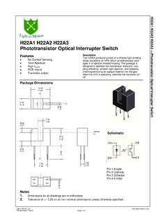
1 dual channel , high Speed Optocouplers Technical Data HCPL-2530 HCPL-0530. HCPL-2531 HCPL-0531. HCPL-4534 HCPL-0534. Features Applications Description 15 kV/ s Minimum Common Line Receivers high These dual channel Optocouplers Mode Transient Immunity at Common Mode Transient contain a pair of light emitting VCM = 1500 V Immunity (>1000 V/ s) and diodes and integrated photodetec- (HCPL-4534/0534) Low Input-Output Capacitance tors with electrical insulation high Speed : 1 Mb/s ( pF) between input and output.
2 TTL Compatible high Speed Logic Ground Separate connection for the Isolation TTL/TTL, TTL/ photodiode bias and output Available in 8 Pin DIP, SO-8, LTTL, TTL/CMOS, TTL/LSTTL transistor collectors increase the and 8 Pin DIP Gull Wing Replace Pulse Transformers Speed up to a hundred times that Surface Mount (Option 020). Save Board Space and Weight of a conventional phototransistor Packages coupler by reducing the base- high Density Packaging Analog Signal Ground collector capacitance. 3 MHz Bandwidth Isolation Integrated Photon Detector Provides Improved Open Collector Outputs Linearity over Phototransistor Guaranteed Performance Type from 0 C to 70 C.
3 Polarity Sensing Safety Approval Isolated Analog Amplifier . UL Recognized 3750 V rms dual channel Packaging for 1 minute (5000 V rms for Enhances Thermal Tracking 1 minute for Option 020) per UL1577. CSA Approved Functional Diagram Single channel Version ANODE 1 1 8 VCC. Available (4502/3, 0452/3). TRUTH TABLE. MIL-PRF-38534 Hermetic CATHODE 1 2 7 VO1. (POSITIVE LOGIC). LED VO. Version Available ON LOW. (55XX/65XX/4N55) CATHODE 2 3 6 VO2 OFF high . ANODE 2 4 5 GND. A F bypass capacitor between pins 5 and 8 is recommended.
4 CAUTION: It is advised that normal static precautions be taken in handling and assembly of this component to prevent damage and/or degradation which may be induced by ESD. 2. These dual channel Optocouplers The SO-8 does not require The HCPL-2531/0531 is designed are available in an 8 Pin DIP and through holes in a PCB. This for high Speed TTL/TTL. in an industry standard SO-8 package occupies approximately applications. A standard 16 mA. package. The following is a cross one-third the footprint area of the TTL sink current through the reference table listing the 8 Pin standard dual -in-line package.
5 Input LED will provide enough DIP part number and the The lead profile is designed to be output current for 1 TTL load and electrically equivalent SO-8 part compatible with standard surface a k pull-up resistor. CTR of number. mount processes. the HCPL-2531/0531 is 19%. minimum at IF = 16 mA. SO-8 The HCPL-2530/0530 is for use in 8 Pin DIP Package TTL/CMOS, TTL/LSTTL or wide The HCPL-4534/0534 is an HCPL-2530 HCPL-0530 bandwidth analog applications. HCPL-2531/0531 with increased HCPL-2531 HCPL-0531 Current transfer ratio (CTR) for common mode transient immunity HCPL-4534 HCPL-0534 the HCPL-2530/0530 is 7% of 15,000 V/ s minimum at minimum at IF = 16 mA.
6 VCM = 1500 V guaranteed. Selection Guide Widebody Minimum CMR 8-pin DIP (300 Mil) Small-Outline SO-8 (400 Mil) Hermetic Current dual Single dual Single Single Single and dV/dt VCM Transfer channel channel channel channel channel dual channel (V/ s) (V) Ratio (%) Package Package* Package Package* Package* Packages*. 1,000 10 7 HCPL-2530 6N135 HCPL-0530 HCPL-0500 HCNW135. 19 HCPL-2531 6N136 HCPL-0531 HCPL-0501 HCNW136. HCPL-4502 HCPL-0452 HCNW4502. 15,000 1500 19 HCPL-4534 HCPL-4503 HCPL-0534 HCPL-0453 HCNW4503.
7 1,000 10 9 HCPL-55XX. HCPL-65XX. 4N55. *Technical data for these products are on separate Agilent publications. Ordering Information Specify Part Number followed by Option Number (if desired). Example: HCPL-2531#XXXX. 020 = UL 5000 V rms/1 Minute Option*. 300 = Gull Wing Surface Mount Option . 500 = Tape and Reel Packaging Option XXXE = Lead Free Option Option data sheets available. Contact your Agilent sales representative or authorized distributor for information. *For HCPL-2530/1 and HCPL-4534 only. Gull wing surface mount option applies to through hole parts only.
8 Remarks: The notation # is used for existing products, while (new) products launched since 15th July 2001 and lead free option will use . 3. Schematic 1 I F1 ICC. VCC. + 8. VF1. I O1. VO1. 7. 2. 3 I F2. I O2. VO2. VF2 6. +. 4. GND. 5. HCPL-4534/0534 SHIELD. USE OF A F BYPASS CAPACITOR CONNECTED. BETWEEN PINS 5 AND 8 IS RECOMMENDED. Package Outline Drawings 8-Pin DIP Package (HCPL-2530/2531/4534). ( ) ( ). TYPE NUMBER 8 7 6 5 OPTION CODE*. ( ). A XXXXZ DATE CODE. YYWW RU. UL. 1 2 3 4 RECOGNITION. ( ) MAX.
9 ( ) MAX. + 5 TYP. - + ). ( - ). ( ) MAX. ( ). ( ) MIN. ( ) MIN. DIMENSIONS IN MILLIMETERS AND (INCHES). *MARKING CODE LETTER FOR OPTION NUMBERS. "V" = OPTION 060. OPTION NUMBERS 300 AND 500 NOT MARKED. ( ) MAX. ( ) NOTE: FLOATING LEAD PROTRUSION IS mm (10 mils) MAX. ( ). 4. Package Outline Drawings, continued 8-Pin DIP Package with Gull Wing Surface Mount Option 300 (HCPL-2530/2531/4534). LAND PATTERN RECOMMENDATION. ( ) ( ). 8 7 6 5. ( ). ( ). 1 2 3 4. ( ). ( ). ( ) ( ). MAX. ( ) MAX. ( ). + - + ). ( ) ( - ).
10 ( ) ( ). 12 NOM. ( ) ( ). BSC. DIMENSIONS IN MILLIMETERS (INCHES). LEAD COPLANARITY = mm ( INCHES). NOTE: FLOATING LEAD PROTRUSION IS mm (10 mils) MAX. Small Outline SO-8 Package (HCPL-0530/0531/0534). LAND PATTERN RECOMMENDATION. 8 7 6 5. ( ). XXX. YWW TYPE NUMBER ( ). ( ) (LAST 3 DIGITS). DATE CODE. 1 2 3 4 ( ). ( ) BSC. ( ) ( ). * 7 45 X. ( ) ( ). ( ) ( ). ( ). ( ). * TOTAL PACKAGE LENGTH (INCLUSIVE OF MOLD FLASH) MIN. ( ) ( ). DIMENSIONS IN MILLIMETERS (INCHES). LEAD COPLANARITY = mm ( INCHES) MAX. NOTE: FLOATING LEAD PROTRUSION IS mm (6 mils) MAX.