Transcription of Duct Bank Heating Calculations are Essential for …
1 LANE COBURN & ASSOCIATES, LLC. Duct Bank Heating Calculations are Essential for Critical Environments (Data Centers). Electrical Heating Calculations may need to be performed when large amounts electrical duct banks with significant amounts of conduits and conductors are routed below grade in the earth. These Heating Calculations are performed to determine if any de rating of the conductors is required. This de rating is based on many factors including but not limited to the following: 1. Number and size of conduits and conductors 2. Configuration of the conduits and conductors 3. Spacing between the conduits in both the horizontal and vertical dimensions 4.
2 Amount of earth above the conductors 5. The RHO factor and the amount of the back fill material 6. Load factor of the conductors 7. The actual design load As in any situation, if the electrical conductors overheat past their rated use, the insulation protecting the conductor could burn off or degrade to a point where a short circuit condition could be precipitated. As defined in this article the Load Factor plays a major role in defining if an installation will have a problem with overheating. A data center environment will typically have a very high Load Factor value, which will lead to significant problems if not designed properly. At Lane Coburn & Associates, LLC, we are beginning to see existing data centers with significant overheating issues.
3 The large underground feeders serving these data centers posed no problems before these critical environments were loaded up to the intended design loads. We are starting to see existing data centers that previously never achieved 50% of the design capacity, now running at or near capacity. Electrical conductor Heating Calculations can be very complicated based on many of the variables noted previously. There are various software programs available for determining the potential de rating of feeder conductors in large electrical duct banks. It is also critical to hire a Professional Electrical Engineer with expertise in both critical environments topology and on providing Neher-McGrath Calculations .
4 ELECTRICAL ENGINEERING D/B TEAM MEMBER LIGHTING DESIGN CONSULTING LEED 1. LANE COBURN & ASSOCIATES, LLC. Definitions utilized in the calculation Load Factor - The ratio of the average load in kilowatts supplied during a designated period to the peak or maximum load in kilowatts taking place in that period. Load factor, in percent, also can be derived by multiplying the kilowatt hours (kWh) in the period by 100 and dividing by the product of the maximum demand in kilowatts and the number of hours in the period. Example: Load Factor calculation - Load Factor = kilowatt hours/hours in period/kilowatts. Assume a 1 day billing period or 1 times 24 hours for a total of 24 hours.
5 Assume a customer used 15,000 kWh and had a maximum demand of 1500 kW. The customer's load factor would be percent ((15000 kWh/24 hours/1500 kW)*100). The % load factor may be representative of a standard commercial building. The load factor in a data center with fairly constant load 24 hours of the day should be significantly higher. RHO Thermal resistivity. Thermal resistivity, as used in the National Electrical Code annex, indicates the heat transfer capability through a substance in the trench by conduction. This value is the reciprocal of thermal conductivity and is typically expressed in the units C-cm/watt. Where an underground electrical duct bank installation utilizes the configurations identified in the National Electrical Code examples, the National Electrical Code indicates in section 310-15 (b), that Calculations can be accomplished to determine actual rating of the conductors.
6 A formula is provided in the National Electrical Code that can be utilized under Engineering Supervision to provide these Calculations . This formula is typically not sufficient because it does not include the effect of mutual Heating between cables from other duct banks. For distinctive duct bank configurations, an electrical system design engineer must utilize the Neher McGrath calculation method. The Neher-McGrath Calculations are very complex and involve many Calculations and equations and can be exceedingly time consuming. In addition, many of the Calculations build on each other, so an error in one part of the calculation can result in a significant error in the final outcome.
7 The hand Calculations become even more complex if cable in the duct bank are of different sizes. I have provided some of the pertinent information directly from the National Electrical Code below: ELECTRICAL ENGINEERING D/B TEAM MEMBER LIGHTING DESIGN CONSULTING LEED 2. LANE COBURN & ASSOCIATES, LLC. National Electrical Code : (B) (1) Formula Application Information. This NEC annex provides application information for ampacities calculated under engineering supervision. The data in Anex B is based on the Neher- McGrath method NEC (B) (2) Typical Applications Covered by Tables. Typical ampacities for conductors rated 0 through 2000 volts are shown in Table through Table Underground electrical duct bank configurations, as detailed in Figure , Figure , and Figure , are utilized for conductors rated 0 through 5000 volts.
8 In Figure through Figure , where adjacent duct banks are used, a separation of m (5 ft) between the centerlines of the closest ducts in each bank or m (4 ft) between the extremities of the concrete envelopes is sufficient to prevent de rating of the conductors due to mutual Heating . These ampacities were calculated as detailed in the basic ampacity paper, AIEE Paper 57-660, The calculation of the Temperature Rise and Load Capability of Cable Systems, by J. H. Neher and M. H. McGrath. For additional information concerning the application of these ampacities, see IEEE/ICEA Standard S-135/P-46-426, Power Cable Ampacities, and IEEE Standard 835-1994, Standard Power Cable Ampacity Tables.
9 You can see that the tables in the National Electrical Code for underground duct banks are very limited. If the RHO or Load Factor values are different that what is stated in the tables, then the tables do not apply. If the configuration of the conduits exceed the 6. electrical ducts as illustrated on Table the tables do not apply. Additionally if other duct banks are closer that 5 feet, the mutual Heating effect of those conductors will not be taken into account. As stated previously, a remedy to the complexity of these Calculations is to utilize a software program. The software will make the math substantially easer but the data the soft input into the software and the calculated result need to be tureally analizedy by speciliced engineeres enperenced with this type of Heating issue.
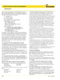
10 ELECTRICAL ENGINEERING D/B TEAM MEMBER LIGHTING DESIGN CONSULTING LEED 3. LANE COBURN & ASSOCIATES, LLC. Figure #1. The diagram above is of a standard trench detail. Electrical Heating becomes more of an issue when multiple rows of conduits are stacked on top of each other. Additionally, the separation of the conduits in both the vertical and horizontal planes as well as the total cover above the top row will all affect the potential de rating of the conductors. As stated above, both the load factor and the RHO value of the back fill also play large roles in determining the potential de rating of the conductors in the duct bank. See examples below.