Transcription of Ductable units - EUROCONFORT
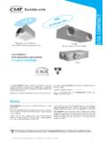
1 MAJOR 2 NCHD uctable units1 AIR CONDITIONING - HEATING - REFRIGERATION - AIR HANDLING - HEAT EXCHANGE - NA BMAJOR 2 NCHis a non independent air conditioning terminalunit for heating and cooling offices and reduced dimensions and designed to ease maintenanceinterventions, the MAJOR 2 NCHadapts to all types 2 NCHprovides the user with thermalcomfort thanks to a high performance compact coil andensures a particulary low acoustic 2 NCHis available in 4 models:- NCH Imodel, rectangular discharge- NCH Ymodel, circular discharge- NCH H model, discharge and circular air recovery(with air recovery plenum)- NCH U model, discharge and lateral air recovery(with air recovery plenum)* see terminal units controlsMAJOR 2 horizontal non-cased model (NCH), is a compromise between the Coadis Slim and the UTA Compact in terms ofcapacity and unit has a sound-proofed expansion box on the outlet, and can cover static pressure up to 90 Pa meeting the requirementsof all air diffusion systems up to 90 Pa.
2 It can also be equipped with lateral circular range includes 6 sizescovering refrigerant capacityranges from to 8 2has 7 operating speeds, three of which are pre-wired in factory. In the standard version, the fan motorassembly speeds and auxiliary electrical elements (2-pipe + 2-wire version) are available on a terminal block without controlunit. MAJOR 2 is easy to use, and can be fitted with optionalfactory fitted and tested CIAT electronic regulation systems forimproved comfort and expenditure control:- MAJOR 2 with V30 electronic MAJOR 2 with V200 electronic MAJOR 2 with V2000 electronic MAJOR 2 with V3000 electronic this configuration, simply connect the water and electricityand immediately feel the benefits of the MAJOR takes part in the EUROVENT fan coil unit certification programme. See performances in Eurovent mode, on last page of the list of products and certified characteristics is given in the EUROVENT directory and on the web site pressure and high capacityductable unitsNCH I NCH YCOADIS COMBI+NCH UMotor optionalAIR CONDITIONING - HEATING - REFRIGERATION - AIR HANDLING - HEAT EXCHANGE - NA BMAJOR 2 NCH2 Ductable unitsTECHNICAL DESCRIPTIONC asingGalvanized sheet metalInsulation in melamine resin, open cells flexible foam, withaluminium film, M1, 10 mm hole for treated fresh air expansion boxintegrated in the unitBottom inspection panels for access and dismantling of theunit s main : one or more 200 mm circular spigots in auto-extinguishable polymer Model.
3 Rectangular sleeve panel with fixation oblong coil (2 or 4-pipe system)New concept of high performance compact coil, with newgeometry sheet tubes, continuous fins in aluminiumHydraulic connectors of coils piping with 40 mm between on the left or right sides of the unit , when facingthe vents and drains integrated in the pressure: 16 bar (at 20 C).Test pressure 24 water temperature: 110 C (PN 10).Electrical battery (2-pipe system +electric)230/1/50 monotubes electrical elements inserted in thealuminium capillary type temperature limiters, manual and automaticreset, inserted in the aluminium blockCondensates recovery drain panPolymer material drain panWithout water retention,condensates drain at the same levelas the drain pan bottom, connectors manually reversible towards the frontor the drainage diameters: 15, 16, 22 or 28 mm in motor assembly Motor7 speeds, 3 are pre-wired in factory(possibility of modifyingthis wiring on site).Enclosed type, tropicalised, with protected shaft and thermal protector with standard thermal cut-out on the supply 230/1 electrical consumption.
4 Fan(s)Galvanized sheet metal dual-inlet impeller(s) with forward-curved blades. V0 fire filterPositioned on the fan coil filtering media in polyester fibers, Class EN 779: resistance: boxEnclosed box on the hydraulic connections side (NCH).Electrical connection terminal box on DIN railing as per EN50022- mm stops for customer's : Refer to installation brochures for futher diam. 200mm discharge sleeve (NCH Y).Intake sleeve for connection to a rectangular plenum with diam. 200 mm intake inlet(s) for ducting(Happlication).Diam. 100 mm smooth sleeve for treated fresh air 100 mm smooth sleeve with self-adjustable module fortreated fresh air mounts for draining DEVICESR ange of wall-mounted electromechanical thermostatsV30 and V200 electronic and V3000 communicating electronic rangeLON control, consult (CONSULT US)- Additional spigots (NCH Y).- Other spigot diameters (NCH Y).- 60 Hz operation (230V).- High Energy Efficiency (HEE) 2 NCHD uctable units3 AIR CONDITIONING - HEATING - REFRIGERATION - AIR HANDLING - HEAT EXCHANGE - NA BDIMENSIONS OF NCH MODEL(RECTANGULAR DISCHARGE)Hydraulic connectionsNOTE.
5 For satisfactory operation a distance of > 250 mmat the unit intake must be respectedMAJOR 2 NCH model IAEAFAGAHAIM asskgDimensional drawing426 N765505535400400 267065443428 N96570573560060030430 N116590593580080040432 N1365110511351000100046434 / 435 N1565130513351200120054 DETAIL AReversible connectorsCondensate drain 15-16-22 and 28 mmDouble deflection rectangulardischarge grille, 426 N, 428 Nand 430 N (others sizes, consult us)Corresponds tothe reservationdimensions in the wallCondensate drainAir filter disassembled from rearRemovable panels for access from below to fan motor unit and coilOblong slots 12,7 x 25 Between axis=725 Pre-stamped hole for freshair (accessory module)Sound-proof expansion box (ready to be placed against a wallwith foam seal accessory for fitting under a structural beam) Electrical connection boxCondensatesrecovery panBetween axis = AGDouble sleeve A-BAcold water coilBhot water coil( 2-pipe system)(4-pipe system)Sleeve OD 150 x AI150 x AHAIR CONDITIONING - HEATING - REFRIGERATION - AIR HANDLING - HEAT EXCHANGE - NA BMAJOR 2 NCH4 Ductable unitsDIMENSIONS OF NCH MODEL(CIRCULAR DISCHARGE)Hydraulic connectionsMAJOR 2 NCH model YAIAJAKM asskgDimensional drawing426 N765505535265976176428 N96570573530430 N116590593540432 N13651105113546434 / 435 N15651305133554 DETAIL AReversible connectorsCondensate drain 15-16-22 and 28 mmX = number of spigotsRemovable panels for access from below to fanmotor unit and coilMax air flow rate advised per 200 outlet: 400 m3/h* See user's brochure foraeraulic balanceCondensates drain2-pre-stampedholes, 200 mmAir filter disassembled from rearOblong slots x 25 Between axis = 725 Pre-stamped hole for conditioned freshair (accessory module)Sound-proofexpansion box Electrical connection boxCondensatesrecovery panBetween axis = AKPLENUM TYPES 200 mm spigot(s)NOTE.
6 For satisfactory operation a distance of > 250 mm at the unit intake must be respectedDouble sleeve A-BAcold water coilBhot water coil( 2-pipe system)(4-pipe system)NCH 426 NNCH 428 NNCH 430 NNCH 432 NNCH 434 / 435 NMAJOR 2 NCHD uctable units5 AIR CONDITIONING - HEATING - REFRIGERATION - AIR HANDLING - HEAT EXCHANGE - NA BDIMENSIONS OFNCH ACCESSORIES FORIANDYMODELSR ecovery sleeve, smooth sheetmetal, rectangular, without insulationRecovery plenum, smooth sheet metal, 200 mm for Happlication, with filterRecovery plenum, smooth sheetmetal 200 for Happlication, withoutfilterNote: In the case of a plenum without filter, the installer shouldallow for his own filter on the recovery air flow rate recommended per 200 outlet: 500 m3/hMAJOR 2 NCHAFX(Number of spigots)426 N4501428 N6502430 N8502432 N10503434 / 435 N12504 200 x XAir filter lodgingto be dismantled underneath the unitAir intake section 200 x AFAir filter lodgingto be dismantled underneath the unit 200 spigot samenumber as air outlets(1 to 4) 200 spigot samenumber as air outlets (1 to 4)Conditioned fresh air knockoutConditionedfresh airknockoutAIR CONDITIONING - HEATING - REFRIGERATION - AIR HANDLING - HEAT EXCHANGE - NA BMAJOR 2 NCH6 Ductable units2411012 Hydraulic connectionsMAJOR 2 NCH U modelALAMANM asskgDimensional drawing426 N*780505535287106685428 N*98070573533 DIMENSIONS OFNCH U MODELS pigots 200 DETAIL AReversible connectorsCondensate drain 15-16-22 and 28 mmRemovable panels for access from below to fanmotor unit and coilCondensates drainAir filter disassembled from rearOblong slots x 25 Between axis = 725 Pre-stamped holefor fresh air(accessory module)
7 Electrical connection boxCondensatesrecovery panBetween axis = ANDouble sleeve A-BAcold water coilBhot water coil( 2 pipe system)(4 pipe system)Spigots 200 Pre-stamped holefor conditioned fresh air 100 or 125 mm* Both sizes are available with an HEE motorPre-stamped holefor conditioned fresh air(accessory module)MAJOR 2 NCHD uctable units7 AIR CONDITIONING - HEATING - REFRIGERATION - AIR HANDLING - HEAT EXCHANGE - NA BTECHNICAL CHARACTERISTICSP iping diameter at fan coil outlets (tapped connectors)The diameters of the female tapped fittings on coil connection pipes are standardised (see above drawing dimension T) MAJOR 2426 N428 N430 N432 N434 N435 N2- pipe sytem Heating or coolingcoil3/8 "3/8 "3/8 "3/8 "1/2"1/2 "4- pipe sytem Cooling coil3/8 "3/8 "3/8 "3/8 "1/2 "1/2 "Heating coil3/8 "3/8 "3/8 "3/8 "3/8 "3/8 "Diameters of valve outlets (threaded connectors)The diameters of the valves male threaded connections are standardised (see above drawing dimension T2)MAJOR 2426 N428 N430 N432 N434 N435 N2- pipe sytem Heating or coolingcoil0,530,760,991,321,581,584- pipe sytemCooling coil0,530,760,991,321,581,58 Heating coil0,130,130,250,200,240,24 Motor electrical characteristics (230/1/50)MAJOR 2426 N428 N430 N432 N434 N435 N2- pipe sytem Heating or coolingcoil1/2 "1/2 "1/2 "1/2 "3/4"3/4"4- pipe sytemCooling coil1/2 "1/2 "1/2 "1/2 "3/4"3/4"Heating coil1/2 "1/2 "1/2 "1/2 "1/2 "1/2 "* Sizes 426 SP N, 428 SP N, 432 SP N characteristics are identical to those of size 434 NFor units fitted with customer s control valves, an intermediate two-part male/female connector is needed between the coilconnector and the valve(s).
8 This connector is available as an accessory (1, 2 or 4 connectors are required depending on theconfiguration (2 or 4-pipe) and the valve type (2-way or 4-way) - consult us).When a CIAT valve-based control system is used, the two-part connector is integrated in the control content (in litres)DN10 unit withvalve (optional)Standard unitNote: images of the valve motors are for information only and are not contractually 2 Motor N428 N430 N432 N434 N435 NAbsorbed power (W)R163101116115149163R255889594132142R3 47737878117124R440636664103106R536585857 9497R6325252518686R7284747457776 Absorbed Current(A)R10,270,440,500,500,650,71R20, 240,380,410,410,570,62R30,200,320,340,34 0,510,54R40,170,270,290,280,450,46R50,16 0,250,250,250,410,42R60,140,230,230,220, 370,37R70,120,200,200,200,330,33 AIR CONDITIONING - HEATING - REFRIGERATION - AIR HANDLING - HEAT EXCHANGE - NA BMAJOR 2 NCH8 Ductable unitsTHERMAL PERFORMANCES FOR NON-CASED MODELSCold water temperature:7 / 12 C,summer air temp.
9 :27 C 50 % RH -Hot water temperature:90 / 70 C,winter air temp:19 C.(1) For higher available pressures, consult us. 40 Pa is the medium static pressure with the nominal air flow rate of an aeraulic network ducted to the inlet and theoutlet. Table with hypothetical sound attenuations of the room and installation of 18dB for 426 N to 430 N and 20dB for 423 N to 435 N for a MAJOR 2 NCH ductedat the intake and discharge. Should the unit not be ducted to the inlet, add 4 dB to the above comfort levels.(2) Please note, the air discharge temperature must not exceed 65 C. (CIAT recommendation)Standard factory wiringMajor 2 NCHM otor flowm3/hAvailablestatic pressure Pa (1)Heating capacity2-pipe systemWCooling capacityWHeating capacity4-pipe systemW coilISO or NRcomfortlevelMean air temperature rise in K (2)Auxiliary electric battery 230 / 1 / 50 TotaleSensible1 R2R426 NR1470407 0302 8902 1604 030336003,81 2007,6R24256 4602 6801 9903 810314,28,4R33755 8102 4301 7803 550284,89,5R43255 1002 1501 5703 250245,511,0R52654 3001 8401 3302 880206,713,4R62103 4801 5101 0802 470<158,517,0R71402 4201 0707521 870<1512,725,5428 NR1665409 8103 5602 7305 520378003,61 6007,1R26059 0603 3202 5205 230353,97,9R35308 1103 0102 2704 850314,59,0R44507 0302 6501 9804 390275,310,6R53806 0802 3301 7303 960226,312,5R63004 9201 9201 4103 400177,915,8R72253 7501 4801 0802 770<1510,621,1430 NR18454014 2005 2103 9607 750381 2004,22 4008,4R274012 7004 7203 5407 170344,89,6R361510 9004 1203 0306 450295,811,6R45109 2003 5602 5705 730257,014,0R54257 8103 0702 1905 090208,416,8R63256 0802 4501 7104 210<1511,021,9R72354 4701 8401 2703 300<1515,230,3432 NR18304014 1005 2103 9505 530341 4005,02 80010,0R272012 5004 6603 4905 080305,811,6R360010 6003 9802 9404 530266,913,9R44958 9203 2002 3804 000208,416.
10 8R54107 4902 5701 9003 5101610,120,3R63256 0501 7901 3702 960<1512,825,6R72354 4201 3301 0502 290<1517,735,4434 NR112204019 2006 8405 2607 430372 0004,94 0009,7R2112517 9006 4304 9207 100345,310,6R3100516 3005 8704 4806 650325,911,8R489014 6005 1803 9806 170296,713,3R574512 5004 3603 3505 520258,015,9R662510 7003 6702 8004 930219,519,0R74658 1802 8502 1304 0301612,825,5435 NR112354019 3006 8905 3507 470372 0004,84 0009,6R2117518 5006 6205 1207 260365,110,1R3107517 2006 1704 7406 900335,511,1R495515 6005 5804 2306 450316,212,4R583513 8004 8903 7505 940277,114,2R668011 5004 0103 0705 210238,717,5R75359 3103 2502 4804 4501811,122,2 MAJOR 2 NCHD uctable units9 AIR CONDITIONING - HEATING - REFRIGERATION - AIR HANDLING - HEAT EXCHANGE - NA BMAJOR 2 HORIZONTALWITHOUT CASINGSTANDARD UNITW ater coil onlyWater coil + electric batteryConnections on the leftConnections on the rightConnections on the left2- pipe + 2 wire system Connections on the right2- pipe + 2 wire system 2- pipe system 4- pipe system2- pipe system4- pipe system1 element 2 elements1 element 2 elementsNCHI Modelwithrectangulardischarge426 NCode5877000587702458770065877030600 W5877048+ 1200 W5877072+ 600 W5877054+ 1200 W5877078 428 N*Code5877001587702558770075877031+ 800 W5877049+ 1600 W5877073+ 800 W5877055+ 1600 W5877079 430 NCode5877002587702658770085877032+ 1200 W5877050+ 2400 W5877074+ 1200 W5877056+ 2400 W5877080 432 N*Code5877003587702758770095877033+ 1400 W5877051+ 2800 W5877075+ 1400 W5877057+ 2800 W5877081 434