Transcription of DUCTILE IRON FLANGED FITTINGS - Canada Pipe
1 DUCTILE iron FLANGED FITTINGSANSI/AWWA-C110 StandardandANSI Class 125 StandardSPECIFICATIONSF langed FITTINGS shown on the pages immediately following are manufactured to either ANSI/AWWA-C110 or to ANSI standard as indicated on each page heading. Elbows or bends ( straight sizes), tees, crosses, concentric reducers, base elbows (except reducing size) and bottom base tees are manu-factured to ANSI/AWWA-C110 standard. These FITTINGS have identical face to face and center to face dimensions and the same flange drilling as ANSI FITTINGS , but differ slightly in wall thickness. DUCTILE iron C110 FLANGED FITTINGS are rated for 150 or 250 psi water working pressure as listed in the radius and reducing elbows, reducing on-the-run tees, side outlet FITTINGS , eccentric reducers and laterals are ANSI Class 125 FITTINGS .
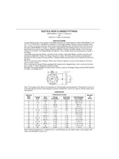
2 DUCTILE iron Class 125 FITTINGS are furnished manufacturer's standard for 250 psi water working pressure. FLANGED offsets and true wyes are furnished manufacturer's do not spot face back of flanges. Where spot facing is required, the back of the flange is machined over its entire ordering any FLANGED FITTINGS equipped with bosses and/or tapped holes, refer to and use the letter key on page ??, which designates location by 125 pound template for drilling shown below is used for all FLANGED FITTINGS whether ANSI/AWWA-C110 or ANSI : The flanges shown above are adequate for 250 psi water working pressure. They should not be con-fused with 250 pound extra heavy flanges covered by ANSI which are rated for 250 psi steam work-ing : Drilling templates are in multiples of four, so that FITTINGS may be made to face in any quarter.
3 Bolt holes shall straddle the center InchesNumberof BoltsFlange CircleFlange Thickness TBolt Hole DiameterBolt Diameterand Length264 3/45/83/4 5/8 x 2 1/4437 1/263/43/4 5/8 x 2 1/24497 1/215/163/4 5/8 x 385108 1/215/167/8 3/4 x 386119 1/217/8 3/4 x 3 1/48813 1/211 3/41 1/87/8 3/4 x 3 1/28101614 1/41 3/161 7/8 x 3 3/4121219171 1/41 7/8 x 3 3/412142118 3/41 3/8l 1/8 1 x 4 1/4121623 1/221 l/41 7/161 1/8 1 x 4 1/216182522 3/41 9/161 1/4 l 1/8 x 4 3/4162027 1/2251 11/l61 1/4 1 1/8 x 520243229 l/21 7/81 3/8 1 1/4 x 5 1/2203038 3/4362 1/81 3/8 1 1/4 x 6 1/228364642 3/42 3/81 5/8 1 1/2 x732 REDUCING DUCTILE iron FLANGED FITTINGSHOW TO ORDERWhen ordering reducing FITTINGS , give the size of the openings in the order indicated by the sequence of the letters a, b, c and d.
4 In designating the size of the openings of side outlet reducing FITTINGS , the size of the side outlet is to be given TEESR educing onReducing onReducing onReducing onOutletOne RunOne Run & OutletBoth RunsREDUCING CROSSESR educingReducingReducing onReducing onononOne RunOne RunOne OutletBoth Outletsand One Outletand Both OutletsREDUCING LATERALSR educing onBranch ReducingTrue YSIDE OUTLET TEESSIDE OUTLET ELBOWSR ight HandLeft HandRight HandLeft HandSPECIAL REDUCING FLANGED FITTINGSTo permit us to ship more promptly, we recommend, wherever possible, the ordering of straight size FLANGED FITTINGS with FLANGED reducer, rather than reducing size FLANGED OF DESIGNATING OF TAPPED HOLES AND/OR BOSSES IN DUCTILE iron FLANGED FITTINGSWhen a DUCTILE iron FLANGED FITTINGS is wanted with a tapped connection, give the size of the tapping required, and designate its location by means of a letter selected from the correct view of the FITTINGS in Elbow90 ElbowTeeCrosseziS thgiartSeziS thgiartSeziS thgiartSssorCeeTwoblE 09 Reducing SizeReducing SizeReducing SizelaretaL 54eeT teltuO ediSwoblE teltuO ediSeziS thgiartSeziS thgiartSeziS thgiartSrecudeR cirtneccEeeT esaBwoblE esaB 09recudeRwoblE 54 Tapping through the wall of the fitting is limited to sizes indicated in the table below.
5 Larger size tapped openings will require casting the fitting with an intergral boss the location of which may also be identified by a letter, as explained above. A boss is always required at V and Y on straight and reducing sizes of 90 elbows, and on all sides of reducers. Maximum Size of Tapped Hole in FittingSize of fitting inches34568101214-36 Size of tap without boss inches3/83/83/81/23/411 1/22 Size of tap with boss inches22 1/22 1/234444*Any tap larger than 4 is threaded for DUCTILE iron - not steel. DUCTILE iron FLANGED FITTINGSANSI/AWWA-C110 StandardBENDSF urnished Faced and Drilled to 125 Pound Template Unless Otherwise Ordered FLANGED 90 BendFlanged 45 BendDIMENSIONS AND WEIGHTS*Five inch size is ANSI 22 1/2 BendFlanged 11 1/4 BendDIMENSIONS AND WEIGHTS Flange accessories must be ordered Diameter InchesPressure Rating psiBodyThickness90 Bend45 BendDimensions InchesApproximate WeightPoundsDimensions InchesApproximate WeightPoundsDuctile 5* 250*.
6 Diameter InchesPressure Rating psiBody Thickness22 1/2 Bend11 1/4 BendDimensionsInchesApproximate Weight PoundsDimensions InchesApproximate iron FLANGED FITTINGSANSI/AWWA-C110 StandardREDUCING ELBOWSF urnished Faced and Drilled to 125 Pound Template Unless Otherwise 90 ElbowDIMENSIONS AND WEIGHTSSIDE OUTLET ELBOWSFor Pressure Ratings and For Drilling Template See Page 52 straight Side Outlet Elbows**In certain sizes, we can furnish side outlet elbows with the side outlet smaller than the main openings where there is of need of such FITTINGS , please check with us before placing your accessories must be ordered Weight PondsNominalPipeSizeInchesDimensions InchesApproximate Weight PoundsTT1 AT T1 A4 x 14 x x.
7 50 16 x .62 x 16 x x .50 16 x .81 x 16 x x .50 18 x .81 x 18 x x .50 105 18 x x 115 20 x x .56 125 20 x .87 x 150 20 x 16 x .56 165 20 x x 190 24 x 14 x 10 .81 .75 220 24 x x 24 x x .62 240 24 x x pipe size InchesDimension T InchesDimension A InchesApproximate weight PoundsNominal pipe size InchesDimension T InchesDimension A InchesApproximate Weight iron FLANGED FITTINGSANSI/AWWA-C110 StandardLONG RADIUS ELBOWSF urnished Faced and Drilledto 125 pound templateStraightReducing90 Long Radius Elbow90 Long Radius ElbowDIMENSIONS AND WEIGHTSFor Pressure Ratings and For Drilling Template See Page 52 straight 45 Long Radius ElbowsFrom ANSI Specification angle designation of an elbow is its deflection from straight line flow and is the angle between the flange accessories must be ordered Pipe Size InchesDimensions Inches
8 ApproximateWeightPoundsNominal Pipe SizeInchesDimensions Inches ApproximateWeightPoundsTT1 BT T1 B3 x .. x x .. x 12 .87 .81 x x .. x .. x 8 .62 x x x .50 x 12 .81 x .. x x .50 x 16 .. x x x .56 x14 .87 x .. x 4 .75 .50 x 18 .. x x x 8 .75 .62 x 16 x .. 23020 x .. x 6 .81 .56 22524 x 14 x 26024 x x 10 .81 .75 x 18 x .. x x 8 .87 .62 x 24 pipe size InchesDimension T InchesDimension M InchesApproximate Weight PoundsNominal pipe sizeInchesDimension T InchesDimension M InchesApproximate Weight iron FLANGED FITTINGSM anufacturer's StandardMeets all Applicable Requirements of ANSI/AWWA-C110 StandardTRUE Y BRANCHESM anufacturer's StandardDIMENSIONS AND WEIGHTR egularly furnished with flanges faced and drilled per template on page 5.
9 Larger sizes can be made to order. Detailed information furnished on request. Flange accessories must he ordered : When ordering reducing FITTINGS , give size of openings in the order indicated by numerals 1, 2 and Diameter InchesWorkingPressure psiDimensions InchesApproximateWeight iron FLANGED FITTINGSANSI/AWWA-C110 StandardTEES AND CROSSESU nless Otherwise Ordered Furnished Faced and Drilled to 125 Pound TemplateDIMENSIONS AND WEIGHTS* Five inch size is ANSI fitting . Flange accessories must be ordered Diameter Inches Pressure Rating psi Dimensions Inches Approximate Weight PoundsRunBranchDuctileT T1 48 .48 *5*250*.50 .50.
10 48 .55 .52 .60 .55 .80 .55 .80 .55 .60 .75 .55 .60 .75 .89 .60 .75 .70 .55 .68 .66 .75 iron FLANGED FITTINGSANSI/AWWA-C110 StandardTEES AND CROSSESU nless Otherwise Ordered Furnished Faced and Drilled to 125 Pound TemplateTeeCrossDIMENSIONS AND WEIGHTSF lange accessories must be ordered OUTLET TEESFor Pressure Ratings and For Drilling Template See Page 55 straight SIDE OUTLET TEES** In certain sizes, we can furnish side outlet tees with the side outlet smaller than the main in need of such FITTINGS , please check with us before placing your accessories must be ordered Diameter Inches Pressure Rating psi Dimensions Inches Approximate Weight.