Transcription of Dynamikkompressor DYC -817
1 Dynamikkompressor externer Dynamikkompressor mit dem SSM2167 von Analog Devices f r dieYaesu-Transceiver FT-817 bzw. FT-818 Bauanleitung2 BX-817-3 Box 73 Amateurfunkservice GmbH 2018 The kit for this dynamic compressor wasoriginally introduced in [1] based on anidea of Phil Salas, AD5X. It was develo-ped especially for the FT-817 (now FT-818), but can also be used for other trans-ceivers with the same microphone interfa-ce, such as the FT-857, FT-897, FT-900 orFT-991. But never use the external com-pressor in combination with the internal ofatransceiver!The dynamic compressor is plugged inbetween the microphone and the transcei-ver. It does not require aseparate powersupply, and can be switched on or off asneeded. No modifications to the originalmicrophone or to the transceiver are integral AF tone generator, which fa-cilitates antenna tuning in SSB mode, canbe keyed via two existing buttons on themicrophone.
2 As aresult, the general prac-tice of whistling for tuning is no longer the exception of one tantalum capa-citor, the SMD components are preassem-bled. Only afew wired components re-main; these can be easily installed even byless experienced Manual for DYC-817 Dynamic Compressor for FT-817/818 When transmitting SSB, adynamic compressor increases average trans-mitted power, and thus the audibility of aweak signal at the distant re-ceiver, by at least one S-unit. This accessory is of special interest toamateur radio operators who work with lower transmitting power or wishto be better heard in 3 Box 73 Amateurfunkservice GmbH 2018 Der Bausatz basiert auf einer Idee von PhilSalas, AD5X, und wurde urspr nglich in[1] vorgestellt. Er war seinerzeit speziellf r den FT-817 (jetzt FT-818) konzipiert,ist aber auch an anderen Transceivern ver-wendbar, die ber die gleiche Mikrofon-schnittstelle verf gen, wie.
3 FT-857,FT-897, FT-900 oder FT-991 und kannggf. alternativ (niemals in Kombination)zum eingebauten Sprachprozessor dieserTransceiver benutzt werden. Der Dynamikkompressor wird in die Lei-tung zwischen Mikrofon und Transceivereingeschleift, ben tigt keine separateStromversorgung und ist bei Bedarf zu-oder abschaltbar. Modifikationen am Ori-ginalmikrofon oder am Transceiver sindnicht integrierte NF-Generator l sst sichmithilfe zweier Tasten am Mikrofon zu-schalten und erleichtert auf diese Weisedas Abstimmen der Antenne in der Sende-art SSB. Das oft praktizierte Abstimm-Pfeifen wird damit berfl SMD-Bauelemente sind, bis auf einenTantal-Elko, bereits vorbest ckt. Es blei-ben somit nur noch einige bedrahtete Bau-teile brig, die sich auch von weniger ge- bten Bastlern einfach verarbeiten lassen.
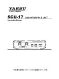
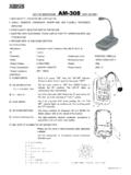
4 Figure 1: Adynamic compres-sor, fully assembledand ready to useBild 1: Dynamikkompressorim fertig aufgebautenund einsatzbereitenZustandEin Dynamikkompressors erh ht bei der Sendeart SSB die durchschnitt-liche Sendeleistung und damit die Verst ndlichkeit eines schwachenEmpfangssignals um mindestens eine S-Stufe. Damit ist dieses Zusatz-ger t speziell f r Funkamateure interessant, die mit kleiner Sendeleis-tung arbeiten oder im Pile-up besser geh rt werden zum Dynamikkompressor DYC-817 Vers. f r FT-817 und FT-818FA-Leserservice 4 BX-817-3 Box 73 Amateurfunkservice GmbH 2018 CircuitFigure 2 shows the AF dynamic compres-sor s schematic. Its central feature is thespecial Analog Devices SSM2167 micro-phone preamplifier. This IC has afixedgain of 18 dB, which is compensated forby the R14/R18 voltage divider.
5 The adjustment resistor P1 in the negativefeedback branch of the low-noise pream-plifier IC1 serves to raise the level of themicrophone signal until it exceeds the no-ise gate of the SSM2167. Quiet (distur-bing) noises can be effectively suppressedin this Switch S1is used to turn the compres-sor function on and off, and along with po-tentiometer P2 sets the desired compres-sion ratio. Three of the four NAND gateson CMOS chip IC2 form the AF generator,which can be activated by simultaneouslypressing the PTT and Down compressor is powered from the inter-nal 5V DC rail of the connected transcei-ver. Current consumption is approximate-ly 10 2: SchematicDYC-817-3BX-817-3 5 Box 73 Amateurfunkservice GmbH 2018 SchaltungIn Bild 2ist die Schaltung des neuen NF-Dynamikkompressors zu sehen.
6 Die ber-arbeitung machte sich erforderlich, da derbisher eingesetzte SSM2165P von AnalogDevicesnicht mehr verf gbar ck ist nunmehr der SSM2167. Erhat eine Grundverst rkung von 18 dB, diemit dem Spannungsteiler R14/R18 kom-pensiert wird. Der Einstellwiderstand P1im Gegenkopplungszweig des NF-Vorver-st rkers IC1 dient dazu, den Pegel desMikrofonsignals so weit anzuheben, bis erdie Ansprechschwelle (Noise Gate) desSSM2167 berschreitet. Leise (St r-)Ge-r usche lassen sich auf diese Weise wirk-sam unterdr cken. Der Schiebeschalter S1 dient zum Ein-und Ausschalten der Kompressorfunktionund mit dem Einstellwiderstand P2 kannman das Kompressionsverh ltnis einstel-len. Drei der vier NAND-Gatter des CMOS-Schaltkreises IC2 bilden den NF-Genera-tor, der durch gleichzeitiges Dr cken derMikrofontasten PTTund Downaktiviertwerden kann.
7 Ihre Betriebsspannung von 5 Vbezieht dieSchaltung vom Transceiver, die Stromauf-nahme betr gt etwa 10 2: Schaltplan des DynamikkompressorsDYC-817-36 BX-817-3 Box 73 Amateurfunkservice GmbH 2018 ConstructionAfter checking all parts against the partslist, you may begin assembly of the circuitboard. You will need atemperature-con-trolled low-voltage soldering iron, 1 mmdia. rosin-cored solder, apair of tweezersand asmall pair of !When working on the board, besure that it is not exposed to undue mecha-nical stress. Strong pressure, which causestransverse deflection on the board, shouldbe avoided. Lengthwise rotation (torsion)should be avoided as RJ45 sockets are already inserted onthe board, so only the eight pins of eachsocket need to be soldered to the boardNext, tantalum capacitor C17 is positive pole is marked with adash,and its correct positioning can be seen inFigures 3 and 5 of the assembly soldering C17, proceed as follows:First, tin the solder pad of the terminal tothe board.
8 Then, center the capacitor andits solder connections over the board s twosolder pads. These have been intentionallydesigned to be slightly larger than neces-sary in order to facilitate soldering the ca-pacitor. Next, heat the previously tinnedsolder pad with asoldering iron and, inthis way, tack it to the capacitor. If thecapacitor is sitting incorrectly, it can stillbe straightened at this stage. If everythingfits, solder the negative pole and subse-quently, the positive is followed by the two potentiometersP1 (2,5 k) and P2 (250 k) and the miniatu-re slide switch S1. Along with the box, thelatter should sit flat on the circuit board sothat the horizontal lever later fits throughthe opening in the , the protruding leads of P1, P2 andS1 located on the solder side in the imme-diate vicinity of the board edge, must becarefully cut flush with the board usingwire cutters so that the board fits nicely in-to the bottom half of the box when 7 Box 73 Amateurfunkservice GmbH 2018 AufbauNach der Pr fung der Vollz hligkeit derwenigen Bauteile anhand der St cklistekann man mit der Best ckung der Platinebeginnen.
9 Dazu werden ein geregelterNiederspannungsl tkolben, 1-mm-L t-draht mit Flussmittelseele, eine Pinzettesowie ein kleiner Seitenschneider ben !Bei Arbeiten an der Platine istdarauf zu achten, dass diese keinen ber-m igen mechanischen Belastungen aus-gesetzt wird. Starker Druck, der zumDurchbiegen der Leiterplatte in Querrich-tung f hrt, ist ebenso zu vermeiden wieein Verdrehen in L ngsrichtung. Die beiden RJ45-Buchsen sind bereits aufdie Platine gesteckt, sodass nur noch diejeweils acht Anschl sse zu verl ten igerweise best ckt man dannden Tantal-Elektrolytkondensator Pluspol ist mit einem Querstrichgekennzeichnet. Seine korrekte Positio-nierung ist sowohl im Best ckungsplanBild 3als auch in Bild 5ersichtlich. Beim Einl ten von C17 geht man wiefolgt vor: Zuerst wird das L tpad des Plus-pols auf der Platine verzinnt.
10 Anschlie-Bild 3: Best ckungsplan des Dynamikkompressors (Oberseite der Platine)Figure 3: Assembly diagram (PCB, top side)8 BX-817-3 Box 73 Amateurfunkservice GmbH 2018 Bild 4: Best ckungsplan der SMD-Bauelemente (Unterseite der Platine)Figure 4: Assembly diagram of the preassembled SMD parts (PCB, bottom side)BX-817-3 9 Box 73 Amateurfunkservice GmbH 2018 end setzt man den Kondensator mit sei-nen L tanschl ssen mittig auf die beidenL tfl chen der Platine. Diese sind absicht-lich etwas gr er als erforderlich dimen-sioniert, um das Einl ten des Kondensa-tors zu vereinfachen. Nun wird das zuvorverzinnte L tpad mit dem L tkolben er-w rmt und auf diese Weise der Kondensa-tor angeheftet . Falls er doch noch schiefsitzen sollte, l sst sich das jetzt noch kor-rigieren.