Transcription of E-97DC:e-97DC 10/5/10 8:27 AM Page 1 Bulletin E-97DC ...
1 E-97DC : E-97DC 10/5/10 8:27 AM Page 1. Bulletin E-97DC . Series dct1000dc dust collector timer controller Specifications Installation and Operating Instructions Thank you for purchasing the Dwyer dct1000dc dust collector timer SPECIFICATIONS. controller . You have selected a state of the art dust collector timer control dct1000dc timer controller : that will provide years of dependable operation and service. Output Channels: 6, 10, & 22 channels. Power Requirements: 10 - 30 VDC. The Dwyer dct1000dc dust collector timer controller was designed to Solenoid Supply: 3A maximum per channel. be used with pulse-jet type dust collectors for on-demand or continuous Fuse: 3A @ 250 VAC. cleaning applications. Temperature Limits: -40 to 140 F (-40 to 60 C). Storage Temperature Limits: -40 to 176 F (-40 to 80 C). Continuous cleaning applications do not require external inputs and can On Time: 10 msec to 600 msec, 10 msec steps.
2 Be used for time based on-demand cleaning through use of the cycle On Time Accuracy: 10 msec. delay feature. Off Time: 1 second to 255 seconds, 1 second steps. Off Time Accuracy: 1% of the value or 50 msec, whichever is For on-demand applications, the plug-in pressure modules greater. (DCP100A/200A) can be used to take full advantage of all the features the Weight: 1 lb oz ( g). dct1000dc offers, or an external pressure switch can be used for High/Low limit control. The Dwyer dct1000dc was designed so that it is easy to use, thus allowing for a quick and easy start up for your dust control applications. The contents inside this installation and operating manual will guide you through the features of the dct1000dc and how they can be applied to get the most out of your dust control requirements. DWYER INSTRUMENTS, INC.
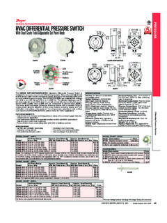
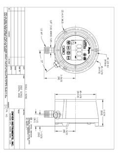
3 Phone: 219/879-8000 BOX 373 MICHIGAN CITY, INDIANA 46361 Fax: 219/872-9057 e-mail: E-97DC : E-97DC 10/5/10 8:27 AM Page 2. 2-3/4. [ ]. PROCESS (IN H2O). LAST OUTPUT. TIME OFF (SEC). TIME ON (M SEC). SETUP STATUS HIGH LIMIT. UP RUN LOW LIMIT. ALARM HIGH ALARM. DOWN RESET LOW ALARM. CYCLE DELAY (MIN). MANUAL. DOWN TIME CYCLES. OVERRIDE (MIN). SELECT AUTO ALARM RESET. (SEC). 6-1/4. [ ]. 6-7/8. [ ]. 1/16. 8-1/4 [ ]. [ ] 8-3/4. [ ]. Figure 1 Dimensional Specifications for the dct1000dc . (shown with optional module DCP100A). 1-13/16. [ ]. 1/2 1. 1-11/16 [ ]. [ ] [ ]. 2-7/16. [ ]. The Dwyer DCP100A or DCP200A pressure modules are designed SPECIFICATIONS. exclusively for use with the dct1000dc dust collector timer controller Pressure Ranges: 10 in or 20 in boards for on-demand cleaning requirements. These series of modules Temperature Limits: -40 to 140 F (-40 to 60 C).
4 Are available in 10 [ kPa] or 20 [ kPa] ranges, which Pressure Limit: 10 psi ( kPa). allow for differential process pressure measurement as indicated on the Pressure Limit (differential): 10 psi ( kPa). display of the master controller . An isolated 4-20 mA readout channel is Accuracy: @ 73 F ( C). provided for remote pressure display. The 4-20 mA output may be wired Output Signal: 4-20 mA. either for use with an external power supply and indicator or using the Alarm Contacts: inductive load, 3A resistive load @ 30 VAC or 40. isolated on-board 24 volt power supply to power the loop. VDC. Process Connections: Two barbed connections for use with 1/8 ( mm) or 3/16 ( mm) tubing. Weight: oz ( g). E-97DC : E-97DC 10/5/10 8:27 AM Page 3. Table of Contents Page No. dct1000dc Terminal Connections Figure 1 Dimensional Specifications.
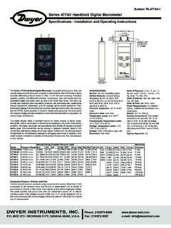
5 2 The line and solenoid connections are located at the lower edge of the Installing the dct1000dc ..3 board below the plastic guard. The terminal block is a Euro style Power Requirements ..3 connector system that clamps the wire within the connector body. The dct1000dc Terminal Connections ..3 connector will accept wire sizes from 14 to 22 AWG. The wire should be External Pressure Connection ..3 stripped to no more than inches to avoid shorts. To assist you in Manual Override Switch Connection ..4 determining the proper strip length, a strip gauge is provided at the lower Down Time Clean Connection ..4 right corner of the board. The connector system used on the dct1000dc . Connecting Multiple timer Boards ..4 is specified for single connection but you can piggyback to a single lug Continuous Cycle Mode ..4 provided that local codes allow for this and good workmanship practices Figure 2 Wiring Connections.
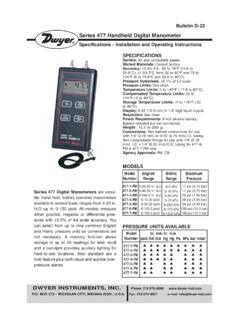
6 4 are followed. To power up the master controller and the channel expander, DCP Installation ..5 connect line power to (+) and (-) (see Dimensional Specifications, Figure Figure 3 DCP Installation ..5 1). Connect the solenoids between the selected output and the solenoid Location ..5 common. Solenoid common and (+) are internally connected. Switches Pressure Model Locking Pins ..5 connected to the control inputs at the top of the board must be isolated Connecting DCP to Master controller ..5 contacts connected only to the relevant terminal and to the common DCP Connections ..5 terminals. The following subparagraphs describe the external switch DCP Maintenance ..5 connections. Refer to figure 2 for switch connection illustration. Alarm Mode Switch Connection ..5. Alarm Reset Switch Connection ..5 External Pressure Connection Connecting the 4-20 mA Loop.
7 5 The controller may be used with an external pressure limit switch or Connecting the Alarm Relay ..6 sensor to provide demand-cleaning operation. The high limit and low limit Three Position Selection Switch Wiring ..6 inputs may be used for this purpose. A simple on-off system can be Programming the dct1000dc Master established with a single pressure switch connected to the high limit input. controller ..6 In this on-demand mode, time on, time off, and cycle delay may be Last Output Setup ..6 programmed to define the cleaning cycle. A three pin terminal block (TB3). Time Off Setup ..6 provides connection for external high and low limit switches (see Figure 2. Time On Setup ..6 on the next page). These switches must be isolated contacts. The High Limit Setup ..7 common line must not be connected to equipment ground or protective Low Limit Setup.
8 7 ground, since these may introduce electrical noise and cause improper High Alarm Setup ..7 operation or possible damage to the control board. The operation of these Low Alarm Setup ..7 inputs are summarized as follows (see next page): Cycle Delay Setup ..7. Down Time Cycles Setup ..7. Auto Alarm Reset Setup ..7 Current Low High Next Maintenance Support and Diagnostics ..7 Operation Limit Switch Limit Switch Operation Restoring Factory Defaults ..7 Hold Open Open Hold Power Indicator ..7 Hold or Run X Closed Run Active Channel Indicator ..7 Hold Open Hold Comm Check Indicator ..7 Hold Closed Run Error Codes ..8 Run Closed Run Glossary of Terms ..8 Hold Closed Run Customer Service Phone Number .. 8 Run Open Hold Transition from open to closed Transition closed to open X Either open or closed Installing the dct1000dc .
9 The open frame design of the dct1000dc will require an enclosure that Note: If a DCP100A or DCP200A pressure module is installed in the meets appropriate safety and local code requirements. For optimal master controller , the switching functions are ignored. performance, the enclosure should also protect the controller from dirt, water and direct sunlight. There are no special orientation requirements, and the controller mounts easily using the mounting holes on the factory installed base plate. Caution: Do not run control wires, communication cables, or other class 2 wiring in the same conduit as power leads. The system may malfunction if class 2 wiring is run together with power conductors. Power Requirements The dct1000dc requires 10 to 30 VDC supply power. The solenoids must be matched to supply voltage.
10 DO NOT exceed 35V, because transient suppression circuitry will begin to draw high current. E-97DC : E-97DC 10/5/10 8:27 AM Page 4. NORMALLY OPEN CONTRACTS. LOW. LIMIT. PRESSURE HIGH. LIMIT LIMIT. SWITCHES. HIGH LOW ALARM MAN D1 ALARM. 4-20 mA CONNECTIONS LIMIT COM LIMIT COM MODE OVR CLN RESETCOM. RECEIVER TB3 TB2. 4-20 MA. OUTPUT. USING DCT1000. 24V SUPPLY. CHAIN. DAISY. OUT. RECEIVER INTERNAL ALARM CONTACTS TB4. MASTER controller . EXTERNAL. SOURCE. 4-20 MA. INPUT MUST NOT BE. CHAIN. DAISY. IN. OPTIONAL. SUPPLY CONNECTION CONNECTED. USING EXTERNAL. POWER SUPPLY. TB5. ALARM. SUPPLY. LOAD dct1000dc . MASTER controller . CHAIN. DAISY. TO ADDITIONAL. OUT. EXPANDER MODULES. CHAIN. DAISY. IN. C3 4. (INTERNALLY CONNECTED). (10 CHANNEL SHOWN). F1. TB1. L1 L2 SOL 1 2 3 4 5 6 7 8 9 10. + - COM. LINE dct1000dc . INPUT. SOLENOIDS SLAVE BOARD.