Transcription of Earth Electrode Testing - jotabill.co.uk
1 02/06/2015 GN3 On-Site Guide Earth Electrode Testing 02/06/2015 It is always the consumers or contractors duty to make sure an insulation is adequately earthed. Under the Electricity Safety, Quality and Continuity Regulations 2002 (ESQCR) a distributor should provide an Earth to new premises, however, it is not the duty of the distributor to provide an existing installation with an Earth . If they do supply one it is still your duty to make sure that is adequate for the installation What we measure when Testing the Earth Electrode is the resistance of the area that is affected by that Electrode . There are two possible ways of Testing for this: Test method 1: DEAD (standard method) Using an Earth Electrode resistance tester Test method 2: LIVE (for RCD s) Using an Earth loop impedance test instrument (this is carried out live and is therefore a more dangerous test!)
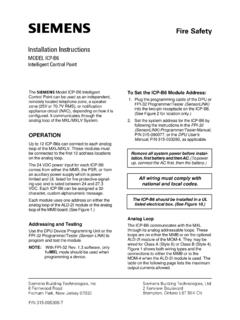
2 Regulation gives no statement of how the test should be carried out Earth Electrode Test ( ) Test Method 1 Earth Electrode Resistance tester 02/06/2015 Earth Electrode Test (Test method 1) Disconnect any earthing conductor on the Electrode . Hammer a temporary rod (current spike) into the ground between 30 m-50 m away from the Earth Electrode under test. Hammer a second temporary rod (potential spike) into the ground at a distance halfway between the Earth Electrode under test and the current spike. Connect terminals C1 and P1 to the Electrode under test Connect P2 to the potential spike. Connect C2 to the current spike. Take a reading. Move the potential spike 3 m-5 m towards the Earth Electrode and take a reading.
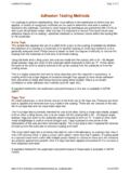
3 Move the potential spike back towards the current spike by the same distance and take a reading. You should get three readings that are similar in value. An average should be taken of these three readings, and this figure is compared to each of the readings taken. Average = reading 1 + reading 2 + reading 3 3 This method is more involved but less dangerous, and involves the use of an Earth Electrode resistance tester Record the average reading on the Schedule of Test Results Test Method 2 Earth Loop Impedance tester 02/06/2015 Testing an Electrode using an Earth Loop Impedance tester (Test method 2) If the installation is part of a TT system and has an RCD protecting it, then an Earth loop impedance tester can be used.
4 A loop impedance tester is connected to the line conductor/s at the source of the TT installation and the Earth Electrode and a test performed. The impedance reading taken is treated as the Electrode It is essential that all the supplementary and main protective bonding conductors are disconnected so that parallel paths don t appear or that the earthing conductor is disconnected from the main Earth terminal. There is an increased level of danger to others whilst this test is being carried out. AFTER THE TEST ENSURE THAT THE EARTHING CONDUCTOR IS RECONNECTED 02/06/2015 Maximum Values of RA The maximum value of the Earth Electrode resistance depends on two key factors. rated residual operating current of the RCD permitted reference voltage (regulation ) 50V In a TT system BS7671 regulation requires that: disconnection time shall comply with the requirements of regulation or regulation ii.
5 Where: is the sum of the resistances of the Earth Electrode and the protective conductor(s) connecting it to the exposed-conductive-part. is the rated residual operating current of the device nIARA nR I 50 V nI02/06/2015 Maximum Values of RA Maximum values of for the basic standard ratings of residual current devices are given in Table BS7671 for a Uo 230V unless the manufacturer declares alternative values. AR02/06/2015 Electrode Resistance Test should be carried out over a 12 or 13 month cycle so that all soil conditions are allowed for. The Electrode resistance can be improved by; Increasing the depth of the Electrode Increasing the number of electrodes (connecting them in parallel) Altering the mineral content of the soil The Earth Electrode resistance can fluctuate due to weather and soil conditions.
6 Maximum Zs values - 200 at consumers Electrode ; 20-21 at distributors 02/06/2015 Electrode Resistance Common 3 mark questions asked: How many tests methods are there Two How many electrodes are used Three Name the electrodes consumers; potential; current How many reading are taken Three What do you do with readings obtained add together and divide by 3 for average Soil conditions least favourable (dry) is preferred