Transcription of Earth Pressure Theory - Civil Engineering
1 Steven F. Bartlett, 2010 Examples of Retaining WallsEarth Pressure TheoryThursday, March 11, 201011:43 AM lateral Earth Pressure Page 1 Steven F. Bartlett, 2011 Let us assume that:wall is perfectly smooth (no shear stress develop on the interface between wall and the retained soil)a)no sloping backfillb)back of the wall is verticalc)retained soil is a purely frictional material (c=0)d)At-rest Earth Pressure :Shear stress are V= b. H= c. H= Ko 1 -sin Normally consolidated (1 -sin OCR-1 = 'vp/ ' conditionAt-Rest, Active and Passive Earth PressureWednesday, August 17, 201112:45 PM lateral Earth Pressure Page 2 Steven F. Bartlett, 2010 Earth Pressure is the lateral pressureexerted by the soil on a shoringsystem. It is dependent on the soil structure and the interactionormovement with the retaining system.
2 Due to many variables, shoringproblems can be highly indeterminate. Therefore, it is essential thatgood Engineering judgment be Earth PressureAt rest lateral Earth Pressure , represented as K0, is the in situhorizontal Pressure . It can be measured directly by a dilatometer test (DMT) or a borehole Pressure meter test (PMT). As these are rather expensive tests, empirical relations have been created in order to predict at rest Pressure with less involved soil testing, and relate to the angle of shearing resistance. Two of the more commonly used are presented (1948) for normally consolidated soils:Mayne & Kulhawy (1982) for overconsolidated soils:The latter requires the OCR profile with depth to be determinedPasted from < g/wiki/Lateral_earth_pressure> At-Rest, Active and Passive Earth Pressure (cont.)Thursday, March 11, 201011:43 AM lateral Earth Pressure Page 3 Steven F.
3 Bartlett, 2010 The at-rest Earth Pressure coefficient (Ko) is applicable for determining the in situ state of stress for undisturbeddeposits and for estimating the active Pressure in clays for systemswith struts or shoring. Initially, because of the cohesive property of clay there will be no lateral Pressure exerted in the at-rest conditionup to some height at the time the excavation is made. However, with time, creep and swelling of the clay will occur and a lateral Pressure will develop. This coefficient takes the characteristics of clay into account and will always give a positive lateral Pressure . This method is called the Neutral Earth Pressure Method and is covered in the text by Gregory Tschebotarioff. This method can be used in FLAC to establish the at-rest condition in the numerical Poisson's ratio of means that there is no volumetric change during shear ( , completely undrained behavior).
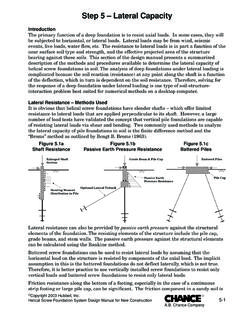
4 Earth Pressure Theory (cont)Thursday, March 11, 201011:43 AM lateral Earth Pressure Page 4 Steven F. Bartlett, 2010 Active and passive Earth pressures are the two stages of stress insoils which are of particular interest in the design or analysis ofshoring systems. Active pressureis the condition in which the earthexerts a force on a retaining system and the members tend to movetoward the excavation. Passive pressureis a condition in which theretaining system exerts a force on the soil. Since soils have a greaterpassive resistance, the Earth pressures are not the same for activeand passive conditions. When a state of oil failure has been reached,active and passive failure zones, approximated by straight planes,will develop as shown in the following figure(level surfacesdepicted).Active and Passive CasesThursday, March 11, 201011:43 AM lateral Earth Pressure Page 5 Steven F.
5 Bartlett, 2010 The Rankine Theory assumes that there isno wall frictionand the ground and failure surfaces are straight planes, and that theresultant force acts parallel to the backfill slope ( , no friction acting between the soil and the backfill). The coefficients according to Rankine's Theory are given by the following expressions:If the backslope of the embankment behind the wall is level ( , = 0) the equations are simplified as follows:The Rankine formula for passive pressurecan only be used correctly when the embankment slope angle equals zero or is negative. If a large wall friction value can develop, the Rankine Theory is not correct and will give less conservative results. Rankine's Theory is not intended to be used for determining Earth pressures directly against a wall (friction angled does not appear in equations above).
6 The Theory is intended to be used for determining Earth pressures on a vertical plane within a mass of Theory -Active and Passive CasesThursday, March 11, 201011:43 AM lateral Earth Pressure Page 6 lateral Earth Pressure Page 7 Steven F. Bartlett, 2010 The amount of displacement to mobilize full passive resistance is about 10 times larger than active (see below).H = height of wallHorz. Displacement (cm)Rankine Theory -Active Case and DisplacementsThursday, March 11, 201011:43 AM lateral Earth Pressure Page 8 Steven F. Bartlett, 2010 Coulomb Theory provides a method of analysis that gives theresultant horizontal force on a retaining system for any slope ofwall, wall friction, and slope of backfill provided This theoryis based on the assumption that soil shear resistance develops alongthe wall and failure plane. The following coefficient is for aresultant Pressure acting at angle.
7 Is the interface friction angle between the soil and the backwall. is the angle of the backslopeCoulomb TheoryThursday, March 11, 201011:43 AM lateral Earth Pressure Page 9 Steven F. Bartlett, 2010 Interface Friction Angles and AdhesionThursday, March 11, 201011:43 AM lateral Earth Pressure Page 10 Steven F. Bartlett, 2010 Interface Friction Angles and AdhesionThursday, March 11, 201011:43 AM lateral Earth Pressure Page 11 Steven F. Bartlett, 2010 Wall DimensionsFill PropertiesTop3ft backf toe concrete150pcf rontw backf from <file:///C:\Users\sfbartlett\Documents\My%20 Courses\5305%20F11\Gravity% > Gravity Wall DesignThursday, March 11, 201011:43 AM lateral Earth Pressure Page 12 Steven F. Bartlett, 2010 Earth PressuresCoulomb ' + Pav' tan (d or f) (half of Pp) ' Moments on WallPav* * * Moments on WallPah * of Wall Design (cont.)
8 Thursday, March 11, 201011:43 AM lateral Earth Pressure Page 13 Steven F. Bartlett, 2010 For multilayer systems or systems constructed in lifts or layers, it is sometimes preferable to place each layer and allow FLAC to come to equilibrium under the self weight of the layer before the next layer is incremental placement approach is particularly useful when trying to determine the initial state of stress in multilayered systems with marked differences in stiffness ( , pavements).It can also be used to replicate the construction process or to determine how the factor of safety may vary versus fill height when analyzing embankments or retaining approach is shown in the following pavement system example Note this approach is not required for homogenous Systems IncrementallyThursday, March 11, 201011:43 AM lateral Earth Pressure Page 14 ;flac 1 -incremental loadingconfiggrid 17,15model mohrgen same 0 20 10 20 same i 1 11 j 1 6gen same 0 25 10 25 same i 1 11 j 6 11gen same 0 30 10 30 same i 1 11 j 11 16gen same same 38 20 38 0 i 11 18 j 1 6gen same same 38 25 same i 11 18 j 6 11gen same same 38 30 same i 11 18 j 11 16mark j 6 ; marked to determine regionsmark j 11 ;marked to determine regionsprop density= bulk= shear= cohesion=0 friction= reg i 2 j 2.
9 Region commandprop density= bulk= shear= cohesion=25e3 friction= reg i 2 j 8prop density= bulk= shear= cohesion=0 friction= reg i 2 j 12set gravity= x i=1fix x i=18fix y j=1his unbal; nulls out top two layersmodel null reg i 2 j 8 ; second layermodel null reg i 2 j 12 ; third layerstep 2000 ; solves for stresses due to first layermodel mohr reg i 2 j 8; assign properties to 2nd layerprop density= bulk= shear= cohesion=25e3 friction= reg i 2 j 8step 2000model mohr reg i 2 j 12; assign properties to 3rd layerprop density= bulk= shear= cohesion=0 friction= reg i 2 j 12step 2000save incremental 'last project state'Steven F. Bartlett, 2010 Building Systems Incrementally (cont.)Thursday, March 11, 201011:43 AM lateral Earth Pressure Page 15 Steven F. Bartlett, 2010 Vertical stress for 3 layers placed incrementallyVertical stress for 3 layers placed all at one timeBuilding Systems IncrementallyThursday, March 11, 201011:43 AM lateral Earth Pressure Page 16 Steven F.
10 Bartlett, 2010 Applied Soil Mechanics with ABAQUS Applications, Ch. 7 More ReadingThursday, March 11, 201011:43 AM lateral Earth Pressure Page 17 Develop a FLAC model of a concrete gravity wall (3-m high, 2-m wide (top) 3-m wide (base)) resting on a concrete foundation. Use the model to calculate the Earth pressures for the cases shown below using the given soil properties. To do this, show a plot of the average Earth Pressure coefficient that develops against the backwall versus dytime. Report your modeling answers to 3 significant figures (30 points). Compare the modeling results with those obtained from Rankine (Mohr-Coulomb)Density = 2000 kg/m^3 Bulk modulus = 25 MpaFriction angle = 35 degreesDilation angle = 5 degreesCohesion = 0 Concrete (Elastic)prop density= bulk= shear= problem 1a, b and c but assume that the friction acting against the back wall of the retaining wall is phi (backfill) divided by 2.