Transcription of EASYDCC System Installation and Command Station Users …
1 EASYDCC System Installation andCommand Station Users GuideVersion 6 SoftwareRelease April 2015 Quick Start Guides - Find Yours - Do It FirstBSSB asic Starter Starter Starter Mounting Command Station User Start Instructions Basic Starter System with Internal Starter System with Plug-in Starter System with Wireless Throttle and Mounting, Hookup and Wiring GuidelinesModular track Fascia plates and the wiring and ZoneMaster Boosters ..24 Using the optional DISTYAMP ..35 Using the optional the track voltage (for Z scale applications)..37 Command Station Operation - Home The Built-In to Multi-unit Advanced Standard Accessory Decoders ..72 Creating and Building Features and Capabilities Of The Command Station - Capabilities Of Service and OPS Programming - Station Memory Performance Command Station s Computer Troubleshooting - of All EASYDCC Command Station Command and reference of ContentsCVP Products Box 835772 Richardson, TX 75083 Website: email: documentation 1996-2015 CVP ProductsAll software 1996-2015 CVP Products2 Basic Starter System - Quick StartContents of the Basic Starter System :- Command Station - ZoneMaster Single Booster- High current power supply DCPS120 and power cord- Low current plug-in wall transformer for Command Station - One 7-foot modular cable- System Installation and Operation Manual- ZoneMaster User GuideIn addition to the above items, you will need about 3 feet of test track, a bit of hookup wire and a locomotive equipped with a DCC compatible decoder.
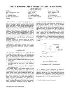
2 Initial Test Track HookupWe strongly suggest that you first hookup the System to a separate section of test track. Once you have used the System and checked it out thoroughly, you can begin permanent Installation knowing that everything is working properly. The Basic Starter System content list and Basic Starter System Quick Start will not include any extra items you may have purchased or upgraded as part of your original purchase. Regardless, the basic hookup and use remains the same. Refer to the instructions that come with the extra Station Rear ViewPower SupplyDCPS120 BoosterModularCableTemporary Test TrackTemporaryProgramming Track12 VACT ransformer3 Basic Starter System - Quick Start continuedAC Wall TransformerWhen connecting the plug from the small wall transformer to the Command Station s AC jack, be sure to push it in as far as it will go. The plug s black plastic strain-relief will be flush to the jack when properly inserted. The small jack is fragile and can be easily damaged.
3 Always pull the plug straight out. Caution: The standard CVP 12 VAC transformer is rated for 110 VAC input CableThe modular cable connects between the Command Station S Boosters jack and the ZoneMaster booster jack labeled DCC DATA BUS. You may use either one of the two data bus jacks. Don t use the OPTO input jack. Do not accidentally plug the cable into the wrong Command Station socket. When plugging the cable into the socket, do not force it. The plug will insert easily and lock with an audible click. To release the plug, push down on the little plastic tab and gently pull the cable out of the socket. DCPS120 Booster Power SupplyThe DCPS120 power supply has a universal AC input. It can use an AC line voltage that ranges from a low of about 100V up to a maximum of about 240 volts. Before using the power supply, set the voltage selector switch to the far left, at the 15V setting. This is the best setting for N, HO, S and O scale locomotives. This setting allows the decoder to drive the motor with about the same voltage as a standard power : Only use the CVP DCPS120 power supply for the ZoneMasters.
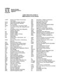
4 Using any other type of power supply will void the warranty and likely damage the booster. ZoneMaster BoosterThe power supply s output cable is thick and heavy and exerts a lot of force on the ZoneMaster input power jack. Be careful not to allow the cable to dangle unsupported from the ZoneMaster input power jack. The Track Output terminal is actually a plug and it can be easily pulled out to make hookup easier. Connect the test track to the output terminal using solid or stranded wire. Small diameter wire is OK for the temporary test track. Command Station Programming TrackThe final two connections hookup up the programming track to the Command Station . This is not necessary for the temporary checkout unless you want to play with decoder programming. Small diameter wire is OK since only one locomotive at a time can use the programming track. You are now ready to power up the System and take it for a test Jack4V6xx T=00 M=255A=0003 B=----Throt A AssignedTo Loco # 0003 Assign ThrotA ToLoco/Cons#___3 Assign ThrotA ToLoco/Cons#____Locomotive direction push button and LED indicatorsSpeed control knobDecoder function controlBasic Starter System - Quick Start continuedPlace Decoder Equipped Locomotive On Test TrackMake sure all wheels are on the rails.
5 If not, there could be a short when power is first applied and the booster short circuit alarm will On The PowerTurn on power to all parts of the System . Watch the Command Station s LCD display for the startup messages. As soon as the startup messages are completed, you will see the standard default display which is called the home page. Rotate the LCD CONTRAST control to obtain the best looking display. Use this control to improve the contrast between the letters and the background. Now check the ZoneMaster. The ZoneMaster GP indicator will be on. The GP s green indicator signifies that it is properly connected to the Command Decoder Address Each locomotive must have a DCC compatible decoder installed. Each locomotive must have a different address. The loco address is just like the address of your house - it is unique. If you purchased a locomotive with a factory installed decoder, the manufacturer will usually program the locomotive address to the locomotive s cab number.
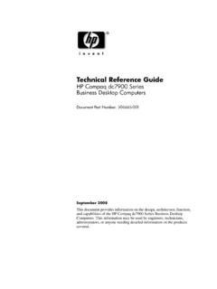
6 If you purchased a decoder separately then it will usually be on the default address of 3. Controlling The Locomotive With Command Station Throttle To control the locomotive, you must assign one of the Command Station s built in throttles to the locomotive address. However, when the Command Station is powered up for the first time, neither throttle A or B are assigned to an address. Therefore the first step is to assign the throttle. For this example the locomotive address will be 3 and it will be assigned to throttle A. If you know your locomotive to be on a different address, then use that address instead. 1. Push the SETUP key. The message shows that it is waiting for additional Push the the THROT-A key which is the 1 key. The Command Station will know automatically that you are wanting the THROT-A function and not just the 1. 3. Push the 3 key followed by the ENTER key to assign throttle A to locomotive address 3. There is no need to include leading zeroes.
7 4. Push ESC to end the key sequence and return the display to the home screen. Notice it shows A is now assigned to address 3. 5. The big black knob under the A is the speed control. The direction key and the indicator lights show the direction the locomotive will move. Turn the speed knob up and observe the locomotive more. Push and release the direction key to change T=00 M=255A=0003 B=---- Setup/Assign What?5 Loco 0003 Fcn#=?Fn=oooooooooooooV6xx T=00 M=255A=0003 B=2920 Controlling Locomotive Decoder Functions - F0 to F9To control locomotive functions such as lighting or sound effects, function keys are used. Push the key labeled FUNCTION for the A throttle. The LCD will show the status for the 13 possible locomotive functions for the locomotive assigned to throttle A. The far left square is function 0 and the far right square is function 12. The open squares indicate the function is not activated. If a square is filled in, the function is on or activated.
8 While the function status display is showing, the Command Station s number keys become the function keys. For example, the 0 key control Function-0 which we shorten to F0. This is typically the headlight and release the 0 key while watching the locomotive headlights. Notice the first square fills in indicating function 0. Push the 0 key again to shut off the headlights. Notice the square shows open. If the decoder also has sound effects, push the 2 key to blow the horn. Pushing and holding the key will continuously sound the horn. Release the key to stop the horn from blowing. Push the ESC key to cancel the function status display and return to the home function status is remembered but the status display can be brought up any time by pushing the function Locomotive Decoder Functions - F10 to F12To activate F10 to F12, first push the SETUP/ASSIGN key to add 10 to any subsequent number key. For example, for F10, push and release SETUP/ASSIGN and then push 0.
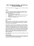
9 Changing The Locomotive AddressRunning two locomotives is a lot more fun than just one locomotive. Adding another locomotive and assigning it s address to Throttle-B is easy. But there is one requirement: the new locomotive must have a different address. Fortunately, this is easily done by using the programming track to change the new locomotive s address. Here s how to do Place the locomotive on the programming track and be sure all wheels are on the Push the SVC PRGM key. This is a severe abbreviation of Service Program. Notice it is asking what do you want to program using the Program Push the key labeled LOCO. The 4 blanks will allow any number from 1 to 9999. For this example, the locomotive decoder will be programmed to address 2920. 4. Push the number keys to put 2920 in the display. Push ENT to program the decoder to the new Push ESC to return to the home page. Move the locomotive back to the main line and assign Throttle-B to the new locomotive address.
10 Speed, direction and function control are the same as with Throttle-A. Loco 0003 Fcn#=?Fn=ooooooooooooo Program Track Program What? Program Track Loco Addr ____? Program Track Loco Addr 2920?F0F12 Basic Starter System - Quick Start continuedThis concludes the Quick Start Section for the Basic Starter System . Please go to page 15 for suggestions on permanently mounting your System as well as recommendations and guidelines for ZoneMaster booster Installation and track Starter System - Quick StartContents of the Extended Starter System :- Command Station - ZoneMaster Single Booster- Extender circuit board with twist-on coax connector and terminator resistor- One plug-in throttle- One Fascia plate with two twist-on coax connectors- High current power supply DCPS120 and power cord- Low current plug-in wall transformer for Command Station - Medium current plug-in wall transformer for Extender- Two 7-foot modular cable- System Installation and Operation Manual- Extender Installation notes- ZoneMaster User GuideIn addition to the above items, you will need about 3 feet of test track, a bit of hookup wire and a locomotive equipped with a DCC compatible decoder.