Transcription of ECEN620: Network Theory Broadband Circuit Design Fall …
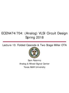
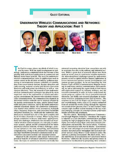
1 Sam Palermo Analog & Mixed-Signal Center Texas A&M University ecen620 : Network Theory Broadband Circuit Design Fall 2012 lecture 17: Divider Circuits Agenda Divider Basics Dynamic CMOS Divider CML Divider Divider Circuit Style Partitioning Asynchronous vs Syncnronous Dividers Dual-Modulus Prescalers Injection-Locked Dividers 2 Charge-Pump PLL Circuits Phase Detector Charge-Pump Loop Filter VCO Divider 3 Loop Divider Time-domain model 4 ( )( )tNtoutfb 1=( )( )( ) ==tNtNtoutoutfb 1dt1[Perrott] out(t) fb(t) Basic Divide-by-2 Divide-by-2 can be realized by a flip-flip in negative feedback Divider should operate correctly up to the maximum output clock frequency of interest PLUS some margin 5 [Perrott] [Fischette] Divide-by-2 with TSPC FF Advantages Reasonably fast, compact size, and no static power Requires only one phase of the clock Disadvantages Signal needs to propagate through three gates per input cycle Need full swing CMOS inputs Dynamic flip-flop may have issues at very low frequency operation (test mode) depending on process leakage 6 True Single Phase Clock Flip-Flop Divider Equivalent Circuit Note.
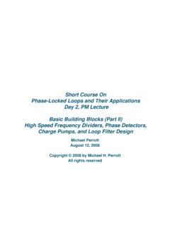
2 Output inverter not in left schematic Divide-by-2 with CML FF 7 Advantages Signal only propagates through two CML gates per input cycle Accepts CML input levels Disadvantages Larger size and dissipates static power Requires differential input Need tail current biasing Additional speedup (>50%) can be achieved with shunt peaking inductors [Razavi] CML Latch When the clock is high (M5 on), the input pair (M1 & M2) tracks (linearly amplifies) the input When the clock is low (M6 on), the regenerative pair (M3 & M4) latches (with positive feedback) the state This regenerative pair continues to provide gain in the store mode, allowing for short cycle operation The minimum cross-coupled pair gain to hold the state is gm3,4RD>1 8 CML Latch When the clock is high (M5 on), the input pair (M1 & M2) tracks (linearly amplifies) the input When the clock is low (M6 on), the regenerative pair (M3 & M4) latches (with positive feedback)
3 The state This regenerative pair continues to provide gain in the store mode, allowing for short cycle operation The minimum cross-coupled pair gain to hold the state is gm3,4RD>1 9 Optimized CML FF for High-Speed Dividers The cross-coupled pair gate and drain capacitances slow down the latch/flip-flop If the flip-flop is switching at high-speed, the regenerative pair gain can actually have a loop gain less than unity due to the short hold state One way to achieve this is by using a different current in the track state (ISS1) and the hold state (ISS2), allowing for smaller regeneration transistors when ISS2 < ISS1 10 CML Latch Swing Control If suitable resistors are not available in a certain process, the PMOS triode-region loads can be used Due to PVT variations, feedback control is generally required to maintain the desired CML logic swing level A replica Circuit produces the required PMOS gate bias to insure the desired CML logic swing for a given ISS Note, triode PMOS loads will generally have more parasitic capacitance than linear resistors.
4 Resulting in a slower Circuit 11 CML Latch with PMOS Diode Loads PMOS diode loads may allow for simpler biasing over PVT variations One issue with this is the large headroom (|VTP|+VOD) required to turn-on the PMOS diode NMOS source followers can allow for similar headroom as with triode loads Another issue stems from the highly non-linear effective resistance which can introduce inter-symbol interference for random data Note, this is not an issue for periodic switching divider applications 12 CML Latch with PMOS Diode Loads PMOS diode loads may allow for simpler biasing over PVT variations One issue with this is the large headroom (|VTP|+VOD) required to turn-on the PMOS diode NMOS source followers can allow for similar headroom as with triode loads Another issue stems from the highly non-linear effective resistance which can introduce inter-symbol interference for random data Note, this is not an issue for periodic switching divider applications 13 CML Divider Clock Swing vs Frequency Interestingly, the divider minimum required clock swing can actually decrease with frequency This is due to the feedback configuration of the divider yielding an effective ring oscillator topology that will naturally oscillate at certain frequency Near this frequency.
5 The input clock amplitude can be very low For frequencies above this natural oscillation frequency, the minimum clock input amplitude increases 14 Divider Circuit Style Partitioning While CML dividers generally operate at the highest speed, the static power consumption reduces their efficiency at lower speeds For large divide ratios, a mixture of CML and static CMOS dividers are often used The first fastest fixed dividers (prescalers) are CML, while the following lower frequency dividers are static CMOS 15 Binary Dividers: Asynchronous vs Synchronous 16 Asynchronous Divider Synchronous Divider Advantages Each stage runs at lower frequency, resulting in reduced power Reduced high frequency clock loading Disadvantage Jitter accumulation Advantage Reduced jitter Disadvantage All flip-flops work at maximum frequency, resulting in high power Large loading on high frequency clock [Perrott]
6 Jitter in Asynchronous vs Synchronous Dividers 17 Asynchronous Synchronous Jitter accumulates with the clock-to-Q delays through the divider Extra divider delay can also degrade PLL phase margin Divider output is sampled with high frequency clock Jitter on divider clock is similar to VCO output Minimal divider delay [Perrott] Dual Modulus Prescalers 18 2/3 MC=0 3 MC=1 2 15/16 Synchronous 3/4 Asynchronous 4 For /15, first prescaler Circuit divides by 3 once and 4 three times during the 15 cycles [Razavi] Injection-Locked Frequency Dividers Superharmonic injection-locked oscillators (ILOs) can realize frequency dividers Faster and lower power than flip-flop based dividers Injection locking range can be limited 19 LC-oscillator type (/2) Ring-oscillator type (/3) [Verma JSSC 2003, Rategh JSSC 1999] [Lo CICC 2009] Injection-locked Frequency Divider Design concept of injection-locked oscillator (ILO) Unwanted harmonics may exist.
7 Self-coupling may produce unwanted tones too. Injection-locked frequency dividers (ILFD) feature lower power consumption and more excellent noise performance than digital dividers. YCLO AMSC-TAMU 20 LPF/BPFFinFoutnFin + mFout LC INFDs Advantage: Better noise performance (LC filtering) Low power consumption Very high operation frequency (~ fmax) Disadvantage: Smaller locking range (LC limited) Unwanted harmonics Large silicon area due to L and C Very difficult to provide multiple phases or large divisor number in one LC oscillator stage (area penalty) Difficult to find an excellent source to inject signal YCLO AMSC-TAMU 21 Ring-Oscillator-Based ILFDs Advantage: Smaller area Wide locking range Small power consumption Disadvantage.
8 Inferior phase noise to LC ILFDs (Still decent) Worse unwanted harmonics (No LC resonant filtering) False locking YCLO AMSC-TAMU 22 Complementary Injection-Locked Frequency Divider (CILFD) Large odd-modulus(101) Only dynamic power consumption 100% frequency locking range Differential input/output 50% duty cycle Small area 23 Fin ( 0 )(2n+1) Fin ( + 0 )(2n+1) Fin ( + 180 )(2n+1)-stageAuxiliary InverterFin ( 180 )Fin ( 0 + 360 /(2n+1) )(2n+1)-stageFin ( 180 + 360 /(2n+1) )Fin ( 0 + 360 (2n)/(2n+1) )Fin ( 0 + 360 (2n)/(2n+1) ) Complementary Injection Scheme Complementary injection reinforces the injection strength to widen the frequency locking range.
9 Only when the inverter transits state the tail transistors inject current. Independent tail injection to each stage avoids the interference between each stage. 24 Injection Signal Ring-oscillator output Tail NMOS injection current Tail PMOS injection current Locking Range (Input Sensitivity) Over 100% locking range(Post-layout simulation in TSMC m technology) 25 Divided-by-3 operation Divided-by-15 operation -10 -8 -6 -4 -2 0 2 4 6 8 0 1 2 3 4 5 6 7 8 Input Power (dBm) Incident Frequency (GHz) -10 -8 -6 -4 -2 0 2 4 6 8 0 1 2 3 4 5 6 7 8 Input Power (dBm) Incident Frequency (GHz) Power Consumption and Phase Noise Power consumption: One ring-oscillator stage: CILFD: The power consumption is independent to the division modulus (# of ring-oscillator stage).
10 Phase noise: The phase noise of CILFD is mainly determined by the phase noise of injection signal. 26 + 1212nfCVPInjDDStage InjDDStagefCVP22 From top to bottom (1) free running CILFD, (2) incident signal, and (3) locked CILFD () )()(NoModulusIncidentPNCILFDPN Example PLL Design Procedure Design procedure for a 100-300 MHz frequency synthesizer Step 1 Determine VCO Tuning Range Needs to be at least the output frequency range plus some margin (10-20%) dependent on PVT tolerance 27 *300 MHz - 100 Range Tuning VCO= *Note if you want the frequency extremes (100 or 300 MHz) you probably want to add some margin here Step 2 Determine Loop Division Ratio, N This is a function of what reference clocks you have access to, loop bandwidth, dominant noise sources 32=N Step 3 Determine Damping Factor Damping factors between and 2 are reasonable, with or 1 commonly chosen = Example PLL Design Procedure Step 4 Determine natural frequency.