Transcription of Economic Load Dispatch and Optimal Power Flow in Power …
1 1 MA5630 Numerical Optimization Final Project Draft Report Title: Economic Load Dispatch and Optimal Power Flow in Power System Team Members: Zagros Shahooei Guna R. Bharati Barzin Moridian 2 Contents 1. Economic Load Dispatch .. 3 2. DC Optimal Power 4 3. AC Optimal Power 6 4. Test systems and 8 Simple 3 Bus Test System .. 8 Introduction to GAMS : .. 9 6 Bus Test System .. 11 Economic Load Dispatch .. 12 DC-OPF .. 12 AC-OPF .. 14 14 BUS Test System: .. 16 5. Conclusion .. 19 3 1. Economic Load Dispatch Electrical energy cannot be stored; it is generated from natural sources and delivered to the demands.
2 A transmission system is used for delivery of electrical energy to the load points. In brief, an interconnected Power system consists of three parts: 1. generators , which produce the electrical energy; 2- Transmission lines, which transmits the produced energy to demands; 3- Loads, which consume the energy. Since it is not possible to store electrical energy, the net energy generation in the system must be equal to the total system load and Power losses. The main objective of Power system is to supply the load continuously and as Economic as possible.
3 Planning the Power generated by each generation unit and the system analysis is done in different steps from weeks until minutes before real time. Economic ( Optimal ) Load Dispatch (ELD) is the process of allocating generation among different generating units; in such a way that the overall cost of generation is minimized. In ELD problem we do not consider the Power losses in transmission lines; so the total Power generation must be equal to the total load. ELD is allocating loads to generation units with minimum cost while meeting the constraints.
4 It is formulated as an optimization problem of minimizing the total costs of generation units. The total cost of generation includes fuel costs, costs of labor, supplies, maintenance. This cost depends on the amount of real Power produced by the generator. Generation cost is considered as a quadratic function. (1) Total costs: (2) The objective function is to minimize the overall cost of Power generation subject to the constraints. (3) Optimization constraints are as follows: Equality constraints: Energy balance equation.
5 The total Power generation must be equal to the demand. (4) Inequality Constraints: generators Power output constraints> (5) 4 2. DC Optimal Power Flow ELD is the simplest planning method and it is used for long-term planning purposes. Most of the system constraints are not considered in ELD. The Optimal Power flow (OPF) problem seeks to control generation/consumption to optimize certain objectives such as minimizing the generation cost or Power loss in the network. Each load or generation point of Power system is called a bus and different buses are connected together with transmission lines.
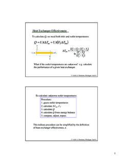
6 Indeed the transmission lines have resistance and reactance which cause Power loss. Considering all the system parameters, the optimization constraints are non-linear equations. To clarify different Power system parameters, a simple 3 bus system is shown in figure 1. Two types of Power exist in Power system, Active Power and Reactive Power . Active Power relates to the resistive loads like electric heaters, lamps, and etc. Reactive lodes are related to motors and rotational loads. Transmission line parameters include resistance and inductance.
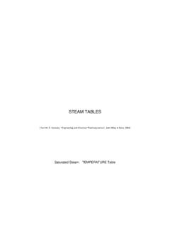
7 Transmission line resistance results in active Power loss and inductance result in reactive Power loss. Figure 1. 3 bus Power system The voltages of each points (bus) in Power system is a sinusoidal wave form with a frequency of 60 Hz. This means the voltage at each bus has an amplitude and a phase angle. The magnitude change of the voltages of different buses is because of transmission line resistance and having different phase angles is a result of transmission line inductance. Figure 2. Sinusoidal voltage waveform 5 Nonlinear AC Optimal Power Flow (OPF) problems are approximated by linearized DC OPF problems to obtain real Power solutions.
8 In DC-OPF, we ignore the line resistances and reactive Power flow in the system. Since the transmission line resistances are considered to be zero, all the voltage magnitudes throughout Power system are equal to the nominal voltage of the system. The voltages are only different in phase angles. The objective function and constraints of DC-OPF are as follows: The objective function is to minimize the overall cost of Power generation subject to the constraints. (6) Optimization constraints are as follows: Equality constraints: o Energy balance equations.
9 For each bus in the system: (7) (8) o Voltage magnitude; for each bus in the system: | | (9) Inequality Constraints: o generators Power output constraints (10) o Phase angle constraints: (11) 6 3. AC Optimal Power Flow The ACOPF is at the heart of Power system operation; it is being done by system operator and is solved form every day for day ahead markets, every hour, and even every 5 minutes. With advances in computing Power and solution algorithms, we can model more of the constraints and remove unnecessary approximations that were previously required to find a solution in reasonable time.
10 Optimal Power flow is sometimes referred to as security constrained Economic Dispatch . As described before, simpler version of OPF, known as DCOPF, assumes all voltage magnitudes are fixed; indeed, DCOPF is a linearized form of a full alternating current network (ACOPF). There are four quantities at each bus: voltage magnitude (V), voltage angle ( ), real Power (P), and reactive Power (Q). In a Power flow solution, buses are classified into three bus types: PQ, PV and slack. PQ buses generally correspond to loads and PV buses to generators . Generator buses are called PV buses because Power and voltage magnitude are fixed; load buses are known as PQ buses because real and reactive Power are fixed.