Transcription of Edwards
1 DIRECT CONDENSATION OFHYDROCARBON VAPORSOCTOBER 6, 1998101 Alexander Ave, Pompton Plains, NJ 07444-0487800-526-5201 973-835-2800 Fax 973-835-2805 Web: E-mail: of the forms enclosed can be filled out at our web siteEdwards ENGINEERING 295-DC-VRU-3I. INTRODUCTIONE veryone who uses solvents in a manufacturing process must also load, unload, andstore them. In doing so, vapors are generated at each step in addition to those generated whenactually using these solvents in a manufacturing process. Edwards Engineering has developedexpertise in all phases of recovering these equipment is based on the Rankine Cycle of refrigeration. All units use refrigerantbased compressors to cool vapors by way of a secondary heat exchanger. This is commonlyknown as the refrigeration or condensation based vapor recovery system. Liquid Nitrogenalso can be used as a refrigerant to cool vapors. When combined with the Rankine Cyclerefrigeration process, this becomes Edwards Engineering s Cryo-Mechanical vapor recoverypackage.
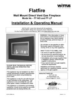
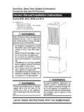
2 In gasoline recovery units, Edwards Engineering now offers a system that combinesRECO very with power GENeration. We are also in the process of developing other innovativedesigns that combine refrigeration with other general, there are two categories of solvent vapor recovery applications: storage/transferrelated and process related. They will be discussed in the following STORAGE SYSTEMSFor a single tank application, the simplest and mosteconomical approach is to mount a vent condensing coil onthe tank itself and to mount the refrigeration equipment onground level near the tank. The condensed vapors can begravity drained back into the tank (Fig-ure 1). In general, by cooling these va-pors to -20oF, a 90-95% recovery canbe attained. For higher efficiencies,lower temperatures may be multiple tank applicationswhere the liquid being stored is the same in all tanks, it is most economical to pipe the vent lines to acommon recovery system and to pump the condensed liquid to a single point.
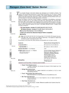
3 (Figure 2)For multiple tank applications where the liquids being stored are of different types, it is usuallydesirable to keep the conden-sate discrete. For this reasonthe best approach is to mount avent condensing coil on eachtank. These vent condensingcoils are then supplied with acold heat transfer fluid from acentral refrigeration system.(Figure 3)In any of the aboveapplications, when tank con-struction precludes mountingvent condensing coils on the tank, they can be mounted at ground level and the condensate is thenpumped back into the ReturnCold SupplyFig. 1 VentCondenserStorage TankCondensed LiquidFig. 2 RecoveryUnitVent to AtmosphereCondensed LiquidTank Vent LineStorage tanks with fixedroofs which vent to atmospherewill contain water vapor in thevapor space which will form hy-drates on the vent condensingcoil. These hydrates will returnto the storage tank after defrost-ing, which may be a Nitrogen blanketing systemis used, it will prevent ambientair and water vapor from en-tering the vapor space.
4 This will eliminate the problem of water being condensed and returning to thestorage tank and will eliminate the need for a defrosting system which in turn reduces the capital cost ofthe recovery TRANSFER SYSTEMSE dwards has supplied hundreds of vapor recovery units for gasoline truck loading terminalssince 1973. We have also supplied a number of similarunits for marine loading vapor recovery systems for vari-ous products (Figure 4). Most of these units have beenof the refrigeration type. Power usage is less than 1 KWH/1,000 gallons loaded for gasoline and KWH/1,000 gallons loaded for distillate. Stand-alone liquid Ni-trogen vapor recovery systems can be provided for bargemounted operation. The small skid size, low power us-age and low maintenance make the liquid Nitrogen VRSideal for barge mounted operation. All marine vapor re-covery systems meet or exceed Coast Guard Regu-lations for facilities (33 CFR 154 Subpart E) and ves-sels (46 CFR 39).
5 Truck loading vapor recovery systemswill meet and exceed EPA regulations 40 CFR Parts 9and 63 dated December 14, are a number of concerns in marine vaporrecovery and truck loading vapor recovery; three of theimportant ones are 1) Safety, 2) Back Pressure, and 3) SafetyCondensation is considered the safest of any con-trol approach currently used. The vapors are simply passed over a cold metal surface and loading regulations require either enrichment of vapors above the UEL (Upper Explosion Level)or dilution below the LEL (Lower Explosion Level) prior to transfer from the vessel to the shore. Con-densation works best by using the enrichment technique so as not to introduce additional cooling loadon the equipment and not require a lower than normal condensation temperature. This enrichment caneasily be done using the product being loaded from storage and passing the vapor stream through thisproduct to saturate the stream. Truck loading doesn't require any enrichment or to AtmosphereCondensedLiquidRefrigerationUn itCold SupplyCold ReturnVentCondensersFig.
6 3 Vapor OutRecoveryUnitVapor InLiquid InLiquidOutVapor OutStorageTanksLiquid InVapor InRecoveryUnitLiquidOutStorageTankFig. 42. Back PressureBack pressure is of major concern due to vapor leakage from a barge/ship or loading truckdesign point. Condensation systems designed by Edwards typically have back pressure in the range of1" to 2" (water column). This low back pressure means in most locations, that no additional blowersare necessary to transport the vapors. Addition of flame arrestors and length of piping may require theuse of a blower EfficiencyCondensation is the most effective vapor control system on the market today. Early units weredesigned to emit no more than 80 mg/liter of gasoline vapor effluent based on the original EPA stan-dards. Second generation systems reduced this to 35 mg/liter. The addition of a Cryogenic third stagewas then introduced to reach the 10 mg/liter EPA requirement, and most recently RECOGEN has beenintroduced to reach emissions levels of less than PROCESS VENT SYSTEMSP rocess vent systems generally fall within four categories:1.
7 REACTORS - Where solvents are used in reactors and are displaced through vent applications are multiple reactor systems which vent to a common recovery MIXERS - Where materials are blended in rotary type mixers and the heat of mixing evaporatessolvent to a vent PAN COATERS - Where materials are coated with a spray solution and the solvent is evaporatedand exhausted to a vent SPRAY DRYERS/GRANULATORS - Where solvents are used as a carrier for agglomeration ofparticles and powders and are subsequently evaporated and exhausted to the of the aforementioned processes generally require temperatures from -20oF to -110oF to at-tain 90% to 95% recovery. For higher efficiencies, lower vapor temperatures down to -300oF may beobtained using our Cryo-Mechanical vapor recovery reactor vents generally are one-pass systems whereby the vapors are exhausted from thereactor, pass through the recovery unit, are cooled, and expelled to the atmosphere.
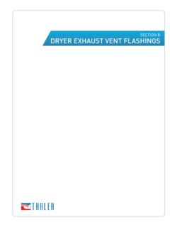
8 In the mixing,coating, and drying/granulating operations, a more efficient and economical method of recovery is touse a closed-loop system. In either case, one important point to consider is the installation of filters sothat dust and other particles are not carried over to the condensing closed-loop system is best utilized on a batch process system, but can be adapted to a con-tinuous feed system. The closed-loop system has the advantage of having no emissions during opera-tion, which in effect gives a 100% recovery of the solvent. The temperature required can be as warm asdesired (+35oF to +60oF) and is only limited by the maximum allowable concentration in the returnstream or LEL concentrations at the end of the cycle. The only emission occurs when the process isopened to empty and refill, or if there is some processes that are continuous feed or cannot be made vapor tight, a modified closed-Fig. 5cDefrostFluidPrecoolerFluidChillerRefri gerationUnitRefrigerationUnitLiquidNitro genUnitDefrostSectionPrecoolerSectionHig h StageLow StageFinal StageLiquidNitrogenCascade Refrigeration SectionTo Vapor CondenserVAPOR RECOVERY SYSTEM: REFRIGERATION/LIQUID NITROGEN SECTIONSCryo-MechanicalUnitDE-UnitAir intakePrecoolerLow TempRefrigerationUnitCondenser AirDefrostAir Vapor InletMain Condensing CoilStripping CoilLiquid MeterPumpDecanterDischargeLN2LN2 UnitLiquidCondensateSCHEMATIC OF Edwards VAPOR RECOVERY SYSTEMFig.
9 5aInletAir/VaporT=AmbientPrecoolerT=40o FT=-100o FT=-300o FMechanicalRefrigVaporCondenserLiquidNit rogenVaporCondenserLiquid OutT=40o FLiquid OutT=-100o FLiquid OutT=-300o FFig. 5bVAPOR RECOVERY SYSTEM: REFRIGERATION/LIQUID NITROGENAIR/VAPOR STREAM loop system may be required. In this case a side stream of air and vapor is pulled out of the closed-loopafter cooling, so that any leakage will be into the system. The solvent vapor present in this side streamnow determines the overall recovery efficiency and the required recommending a condensation unit to a potential user, the primary concern is the characteris-tics of the process stream introduced into the vapor recovery unit so that sufficient refrigeration andheat transfer capacity can be calculated. This allows for simple straightforward design, construction,operation and maintenance of the vapor recovery order to make the proper recommendation of unit size, the following information is required:1.
10 The components of the vapor The concentration of the various The volume flow rate of the stream; cfm, gpm, or Inlet temperature & Desired Hours of condensation based vapor re-covery, the VOC s are recovered as aliquid. If the inlet vapor stream containsmore than one condensable vapor, therecovered liquid will contain the samemixture of components, depending onthe outlet vapor temperature. If theVOC s are immiscible with water, con-densate can be gravity separated andthe water free product can be returned to storage. If these liquids are miscible with water, the mixturemust be separated or disposed of. (Figure 5a, b, c)IV. TEMPERATURESThe temperatures required to re-cover 95% or 99% of a given vapor dependprimarily on the type of vapor involved. Mostchlorinated hydrocarbons encountered intank breathing can be recovered with a 95% efficiency by cooling to -20oF. Different applications mayrequire lower temperatures, such as reactor vent recovery which generally requires temperatures of -60oF to -200oF.