Transcription of EECS150: Finite State Machines in Verilog
1 eecs150 : Finite State Machines in VerilogUC Berkeley College of EngineeringDepartment of Electrical Engineering and Computer Science1 IntroductionThis document describes how to write a Finite State machine (FSM) in Verilog . Specifically, in eecs150 ,you will be designing Moore Machines for your project. This document only discusses how to describeMoore Machines are very useful because their output signals are synchronized with the clock. Nomatter when input signals reach the Moore machine , its output signals will not change until the risingedge of the next clock cycle. This is very important to avoid setup timing violations. For example, ifa Mealy machine s input signal(s) changes sometime in the middle of a clock cycle, one or more of itsoutputs and next State signals may change some time later. Some time later might come after thesetup time threshold for the next rising edge. If this happens, the registers that will hold the FSMs nextstate may receive garbage, or just incorrect inputs.
2 Obviously, this amounts to a bug(s) in your FSM. Avery painful and difficult-to-find bug at tradeoff in using the Moore machine is that sometimes the Moore machine will require morestates to specify its function than the Mealy machine . This is because in a Moore machine , outputsignals are only dependent on the current State . In a Mealy machine , outputs are dependent on boththe current stateandthe inputs. The Mealy machine allows you to specify different output behavior fora single State . In eecs150 , however, the FSMs that you will be designing do not typically have enoughstates for this to create a significant problem. We will err on the side of caution, and vie for a safe butsometimes more verbose FSM implementation, in this MotivationEECS150 is concerned with circuit design. You will be using Verilog to describe your circuits. Unfor-tunately, Verilog , being originally designed to support circuit simulation rather than circuit synthesis, ischalked full of syntactical idiosyncrasies that, if not properly understood, will create odd bugs in yourdesigns.
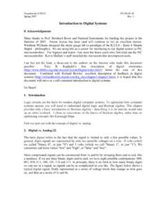
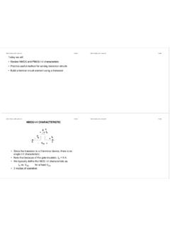
3 This document will show you how to write a Moore FSM in a template-based fashion. This cookie-cutter approach is designed to avoid Verilog s bug-prone areas, while keeping your code as non-verbose as possible. Verilog is a means to an end. This document will show you how to get to the point:designing circuits; while fighting Verilog as little as A Basic FSMF igure1depicts an example Moore FSM. You can tell that this is a Moore machine because the outputsare shown inside [..]s instead of on State transition arcs. The following sections will refer to Figure1asan example use-case for the Moore machine FSM FSM shown in Figure1is useful because it exemplifies the concept of an initial with non-conditional outward with conditional outward must always be an initial State for the FSM to start at after 1A basic FSM!(A & B)!((!A & B) | (A & !B))A & !B!A & BA!AA & BResetSTATE_1[Output1]STATE_2[Output1, Output2,Status = 3'b010]STATE_3[Status = 3'b011]STATE_InitialSTATE_4&logicaland|l ogicalor!
4 That loop back onto with no outward would like to be able to express this type of behavior in a Verilog -written The FSM in VerilogIn looking at Figure1, we will need a way to express the following in State encoding for each mechanism for keeping track of the current from State to values based on the current will construct the FSM one step at a : Creating a State EncodingWe will create our State encoding with Verilog parameters. Parameters are symbolic constants witheither global (given by the Verilog keywordparameter) or module (localparam) scope. Because we onlywant our State encoding to be visible to the module in which we will write the FSM, we will use thelatter:localparam. With this in mind, we can specify 1 The State encoding (in decimal)1localparamSTATE_Initial = 3 d0 ,2 STATE_1 = 3 d1 ,3 STATE_2 = 3 d2 ,4 STATE_3 = 3 d3 ,5 STATE_4 = 3 d4;In Program1, the3 dnotation indicates that the number specified is in the decimal radix.
5 If we wereto use3 b, the encoding would look like that shown in Program2. Both implementations are 10, or3 d, is typically easier to this FSM has 5 total states , we must allocate 3 bits to specify the encoding (hence3 das opposed to2 dor4 is extremely you specify too few bits for your stateencoding, Verilog will not warn you. In fact, when synthesized, each State will only get as many bits asyou provide. For example, ifSTATE_4was specified like this:STATE_4 = 2 d4,STATE_4would be specifiedas00, the bottem 2 bits of what was intended, 2 The State encoding (in binary)1localparamSTATE_Initial = 3 b000 ,2 STATE_1 = 3 b001 ,3 STATE_2 = 3 b010 ,4 STATE_3 = 3 b011 ,5 STATE_4 = 3 b100;As 3 bits can specify a total of 8 states (0-7), our encoding specifies 3 potential states not specifiedas being actual states . There are several ways of dealing with this it, and always pressResetas a way of initializing the these states , and make non-conditional transitions from them to reduce ambiguity, we will choose the second option, which makes our final State encoding thatshown in 3 The State encoding with place-holder states (in decimal)1localparamSTATE_Initial = 3 d0 ,2 STATE_1 = 3 d1 ,3 STATE_2 = 3 d2 ,4 STATE_3 = 3 d3 ,5 STATE_4 = 3 d4 ,6 STATE_5_PlaceHolder = 3 d5 ,7 STATE_6_PlaceHolder = 3 d6 ,8 STATE_7_PlaceHolder = 3 d7;This is a simple encoding:STATE_Initialis assigned 0,STATE_1is assigned 1, etc.)
6 This is notoptimal if State minimization can be performed on the FSM (taught at the end of eecs150 ). We donot recommend applying State minimization techniques by hand, however. They have the tendancy tointroduce bugs and create cryptic FSMs that cannot be easily understood by human readers. This defeatsone of the large pros of Verilog : human readability. Furthermore, the Synthesis tools that compile anFSM, written in Verilog , perform State minimization automatically. Only perform State minimizationmanually to the extent that the function of the FSM remains : Keeping Track of the Current StateWe have several options in how to store the current State of our FSM. The first option is to instantiate amodule that acts as a register and use its output value as our current State . Alternatively, we can createaregelement of the appropriate width and use its value as our current State . We will use the secondmethod for the remainder of this tutorial, out of personal preference.
7 As such, we will store the currentstate as depicted in 4 Storing the current State in areg1reg[2:0] CurrentState;If this material seems unfamilar, read , which explains the difference betweeenwireandregelements in this material is familiar, feel free to skip to in the difference betweenwireandregin Verilog , and when to use each ConventionsThroughout this tutorial, similar terms are used to describe different concepts. These possible sourcesof confusion are explained below:Module Instantiation: Refer to modules instantiated in other modules. Program5shows examplesof input/output ports for a simple module Declaration: Refer to the actual Verilog code written for a module. Program6showsexamples of inputs/outputs within a module declaration. Notice that each input and outputis declared twice in the code. This is important so that inputs and outputs can be assignedparameterizable widths (in this example, Width is used as an example parameter).
8 Program 5 Module #( .Width( ..))2 SentReg (. Clock( ..), ( ..), ( ..), (..), ( ..), ( ..));//OUTPUT portProgram 6 Module (In, Out); = 32; [Width -1:0] In , Out; (Combinational logic)wireelements are simple wires (or busses/bit-vectors of arbitrary width) in Verilog designs. The followingare syntax rules when are used to connectinputandoutputports of a moduleinstantiation together withsome other element in your are used asinputs andoutputs within an actual module must be driven by something, and cannot store a value without being driven. Inother words,wireelements are a stateless way of connecting two peices in a Verilog -based cannot be used as the left-hand side of an=or<=sign in are the only legal type on the left-hand side of can only be used to modelcombinational various legal uses of 7 Legal uses of thewireelement1wireA, B, C, D, E;//simple1-bitwidewires2wire[8:0] Wide;//a9-bitwidewire3regI;45assignA = B //usingawirewithanassignstatement67alway s@(BorC)begin8I = B | C;//usingwiresontheright-handsideofanalw ays@9//assignment10end1112mymodule MyModule (.)
9 In (D), (E)); (Combinational and Sequential logic)regare similar to wires, but can be used to store information ( State ) like registers. The following aresyntax rules when be connected to the inputport of a moduleinstantiation. Note thatregcannotconnect to theoutput port of a module be used asoutputs within an actual module declaration. Note thatregcannotbe used asinputss within an actual module the only legal type on the left-hand side of the only legal type on the left-hand side of aninitialblock=sign (used in Test Benches). be used on the left-hand side of be used to create registers when used in conjunction therefore, be used to create bothcombinational and sequential various legal uses of 8 Legal uses of theregelement1wireA, B;2regI, J, K;//simple1-bitwideregelements3reg[8:0] Wide;//a9-bitwideregelement45always@(Aor B)begin6I = A | B;//usingaregastheleft-handsideofanalway s@7//assignment8end910initialbegin//usin gareginaninitialblock11J = 1 b1;12#113J = 1 b0;14end1516always@(posedgeClock)begin17 K <= I.
10 WhenwireandregElements are Interchangablewireandregelements can be used interchangably in certain can appear on the right-hand side ofassignstatements can be connected to the inputports of module : Transitioning from State to StateAfter we have established our State encoding and a means of storing the current State value (which willhenceforth be referred to asCurrentState), our next task is to create a way for the FSM to actuallychange State , and for it to choosehowto change State . This material requires that you be thealways@block is unfamilar, read , which explainsalways@block in thealways@block is familiar, feel free to skip to @Blocks in @blocks in Verilog , and when to use the two major flavors ofalways@block, namely thealways@( * @Blocksalways@blocks are used to describe events that should happen under certain @blocksare always followed by a set of parentheses, abegin, some code, and anend. Program9shows a 9 The skeleton of analways@block1always@(.))