Transcription of Effect of Fin Shape on GIDL and Subthreshold …
1 IJSTE - International Journal of Science Technology & Engineering | Volume 1 | Issue 10 | April 2015 ISSN (online): 2349-784X All rights reserved by 135 Effect of Fin Shape on GIDL and Subthreshold Leakage Currents Daughty Abraham Abraham George PG Student Assistant Professor Department of Electronics & Communication Engineering Department of Electronics & Communication Engineering Saintgits College of Engineering Saintgits College of Engineering Deepa Gopinadh PG Student Department of Electronics & Communication Engineering Saintgits College of Engineering Abstract FinFETs have emerged as the solution to short channel effects at the 22-nm technology node and beyond. Here, the Effect of fin Shape on the leakage currents like Gate Induced Drain Leakage and Subthreshold leakage is evaluated.
2 The fin Shape can be changed by varying the top width of the fin. Hence, the leakage currents are verified using their expressions for both rectangular and triangular FinFETs. The effects of oxide thickness, drain doping concentration and mobility on these leakage currents are also studied. Keywords: FinFETs, Gate Induced Drain Leakage, Subthreshold leakage _____ I. INTRODUCTION As device feature sizes enter the nanometre regime, leakage power consumption in VLSI systems has become one of the main barriers to technology scaling. Precise modeling of leakage current under process variations is crucial for the proper estimation of leakage power consumption and the optimal design of leakage-sensitive circuits. Double-gate FinFET transistors are recognized as one of the most promising successors of traditional planar bulk devices in the sub-50nm regime due to the significantly reduced leakage current , excellent short channel behaviour, and a fabrication process which is compatible with existing SOI or bulk technology processes.
3 One of the major differences between a FinFET device and a planar device is the fact that the FinFET device consists of multiple small unit fins. Minimization of transistor off-state leakage current is an especially important issue for low-power circuit applications. Leakage mechanisms include Subthreshold leakage, gate oxide tunneling leakage, junction leakage, hot-carrier injection leakage, gate-induced drain leakage, and punch-through leakage currents. A large component of off-state leakage current is gate induced drain leakage (GIDL) current , caused by band-to band tunneling in the drain region underneath the gate when there is a large gate-to-drain bias, there can be sufficient energy-band bending near the interface between silicon and the gate dielectric for valence-band electrons to tunnel into the conduction band.
4 GIDL imposes a constraint for gate-oxide thickness scaling because the voltage required causing this band-to-band tunneling leakage current decreases with decreasing gate oxide thickness, and GIDL can pose a lower limit for standby power in memory devices. GIDL current becomes less significant for digital logic applications as the power-supply voltage is reduced to below (corresponding to the energy band gap of silicon); however, it is still an important consideration for applications such as dynamic random access memory (DRAM), for which data retention time is significantly degraded by GIDL current . Subthreshold leakage current is the dominant mechanism in 90 nm and 65 nm technologies. It increases linearly as technology scales down.
5 Subthreshold current , also known as weak inversion conduction current , between source and drain in a MOS transistor occurs when the gate voltage is below the transistor threshold voltage (Vth). The carriers move by diffusion along the surface, and there is an exponential relation between driving voltage on the gate and the drain current . In this paper, fin Shape significantly impacts leakage in bulk tri-gate nFinFETs with thin fin widths when the fin body doping is optimized to minimize leakage. Here, GIDL and Subthreshold leakage current is observed when varying the fin Shape . The various parameters that these leakage currents are depending are also studied. The detailed description of GIDL and Subthreshold leakage currents are presented in the first part of Chapter 2, followed by the description of processing of the fin-structures on bulk silicon wafers.
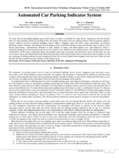
6 Chapter 3 gives the analytical procedures of this project. Simulation results are discussed in Chapter 4. Finally, Chapter 5 gives the conclusion. Effect of Fin Shape on GIDL and Subthreshold Leakage Currents (IJSTE/ Volume 1 / Issue 10 / 027) All rights reserved by 136 II. LITERATURE REVIEW Sources of Leakage Currents: physical phenomena contribute to the leakage currents causing the static consumption when one or more transistors in the Vdd to Gnd paths are in OFF- state. Figure shows the contribution of different leakage currents in a transistor. Fig. : Leakage components in a transistor (Farzan Fallah et al., 2010) Gate Induced Drain Leakage (GIDL): some nanometric technologies, gate induced drain leakage current (IGIDL) may appear. The carriers responsible for GIDL originate in the region of the drain that is overlapped by the gate.
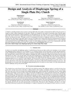
7 IGIDL is caused by the effects of high electric field in this region, when the gate is grounded and the drain is at Vdd. IGIDL current of an nMOS transistor flows from drain to the substrate. Fig. : Drain overlapped MOSFET: GIDL occurs in this region ( FinFETs and Other Multi-Gate Transistors , by Jean Pierre Colinge) Several possible mechanisms contribute to this current . These include thermal emission, trap-assisted tunneling and band-to-band tunneling. It is the Band to Band Tunneling (BTBT) that has the MOSFET relevance at the voltages and structures of modern devices. Consider a MOS structure as shown in figure In the structure gate overlaps the drain junction. As gate becomes more negative or say drain becomes more positive at a fixed gate voltage then p-n+ junction become reverse biased.
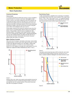
8 Due to reverse biased p-n+ junction, a depletion region forms near the drain junctions. Since the drain is heavily doped, the depletion region width formed inside the drain tends to be narrow, so band to band tunneling will start in this region, electrons tunnel from the valence band of p region into conduction band of n+ region. The removal of electron from valence band produces a hole, which creates electron-hole pairs. Hence, a significant current flow can occur, called GIDL current ( Electronic Devices and Integrated Circuits , by Singh). Fig. : Energy band curvature in the depleted drain region and electron tunneling from the valence band to the conduction band ( Physics of Semiconductor Devices , by Jean Pierre Colinge and C. A. Colinge) Effect of Fin Shape on GIDL and Subthreshold Leakage Currents (IJSTE/ Volume 1 / Issue 10 / 027) All rights reserved by 137 This current may be further enhanced because the generated carriers are accelerated by the longitudinal electric field in the drain substrate junction and this causes impact ionization.
9 For direct-band gap materials, JGIDL can be modelled by equation ( FinFETs and Other Multi-Gate Transistors , by Jean Pierre Colinge). ( ) ( ) Where, A is a pre-exponential parameter given by equation and B is a physically-based exponential parameter given by equation ( FinFETs and Other Multi-Gate Transistors , by Jean Pierre Colinge.). ETOT is the electrical field at point the maximum band-to-band tunneling. ( ) ( ) ( ) ( ) ( ) Where, Eg is the energy band gap of the semiconductor channel and has a strong influence on the band-to-band tunneling current , mr is * mass of electron, q is the charge of electron, = h/2 , h is the Planck s constant.
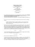
10 A large component of the ETOT is the surface electrical field ES. ES is defined by equation ( FinFETs and Other Multi-Gate Transistors , by Jean Pierre Colinge.). ( ) Where, VDG is the drain to gate bias, VFB is the flat-band voltage, Egap is the energy band gap of silicon, tox is the thickness of the oxide, Si is the permittivity of silicon and ox the permittivity of the oxide. Fig. : Energy band curvature in the depleted drain region and electron tunneling from the valence band to the conduction band ( Physics of Semiconductor Devices , by Jean Pierre Colinge and C. A. Colinge) Subthreshold Leakage current : a MOS transistor, if the gate voltage with reference to the source voltage (VGS) is above the threshold voltage (Vth) then the dominant mechanism of the drain current is primarily drift based.