Transcription of Effluent Treatment Plant (ETP) - IIT Delhi
1 Effluent Treatment Plant (ETP) Presentation by:Dr. GazalaHabibDepartment of Civil EngineeringIIT DelhiWhat is an ETP?INFLUENTETPTREATMENTEFFLUENTSLUDGE ETP(EffluentTreatmentPlant)isaprocessdes ignfortreatingtheindustrialwastewaterfor itsreuseorsafedisposaltotheenvironment. Influent: Untreatedindustrial waste water. Effluent : Treatedindustrial waste water. Sludge: Solid part separated from waste water by of ETP Tocleanindustryeffluentandrecycleitforfu rtheruse. Toreducetheusageoffresh/potablewaterinIn dustries. Tocutexpenditureonwaterprocurement. TomeettheStandardsforemissionordischarge ofenvironmentalpollutantsfromvariousIndu striessetbytheGovernmentandavoidheftypen alties. of ETPThe design and size of the ETP depends upon: Quantity and quality of the industries discharge Effluent .
2 Land availability. Monetary considerations for construction, operation & maintenance. Area dimension depends on: Quality of wastewater to be treated, Flow rate Type of biological Treatment to be used . In case of less available land, CETP (Common Effluent Treatment Plant ) is preferred over ETPT reatment Levels & Mechanisms of ETP Treatmentlevels: Preliminary Primary Secondary Tertiary(oradvanced) Treatmentmechanisms: Physical Chemical BiologicalPreliminary Treatment levelPurpose: Physical separation of big sized impurities like cloth, plastics, wood logs, paper, : Screening:Ascreenwithopeningsofuniformsi zeisusedtoremovelargesolidssuchasplastic s, Sedimentation:Physicalwatertreatmentproc essusinggravitytoremovesuspendedsolidsfr omwater.
3 Treatment Level Purpose:Removaloffloatingandsettleablema terialssuchassuspendedsolidsandorganicma tter. Methods:Bothphysicalandchemicalmethodsar eusedinthistreatmentlevel. Chemicalunitprocesses: Chemicalunitprocessesarealwaysusedwithph ysicaloperationsandmayalsobeusedwithbiol ogicaltreatmentprocesses. Chemicalprocessesusetheadditionofchemica lstothewastewatertobringaboutchangesinit squality. Example:pHcontrol,coagulation, Control: To adjust the pH in the Treatment process to make wastewater pH neutral. For acidic wastes (low pH): NaOH, Na2CO3, CaCO3or Ca(OH)2. For alkali wastes (high pH): H2SO4, HCl. Chemical coagulation and Flocculation: Coagulation refers to collecting the minute solid particles dispersed in a liquid into a larger mass.
4 Chemical coagulants like Al2(SO4)3{also called alum} or Fe2(SO4)3are added to wastewater to improve the attraction among fine particles so that they come together and form larger particles called flocs. A chemical flocculent (usually apolyelectrolyte) enhances the flocculation process by bringing together particles to form larger flocs , which settle out more quickly. Flocculation is aided by gentle mixing which causes the particles to collide. Primary Treatment Level ( ) Secondary Treatment Level Toremove,orreducetheconcentrationoforgan icandinorganiccompounds. Biologicaltreatmentprocesscantakemanyfor msbutallarebasedaroundmicroorganisms, Aerobictreatmentprocessestakeplaceinthep resenceofair(oxygen). Utilizesthosemicroorganisms(aerobes), , Theanaerobictreatmentprocessestakeplacei ntheabsenceofair(oxygen).
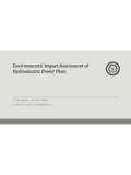
5 Utilizesmicroorganisms(anaerobes)whichdo notrequireair(molecular/freeoxygen)toass imilateorganicimpurities. sludge processTertiary / Advanced TreatmentPurpose:Finalcleaningprocesstha timproveswastewaterqualitybeforeitisreus ed, :Removesremaininginorganiccompounds,ands ubstances, ,virusesandparasites,whichareharmfultopu blichealth, : Alum:Usedtohelpremoveadditionalphosphoru sparticlesandgrouptheremainingsolidstoge therforeasyremovalinthefilters. Chlorinecontacttankdisinfectsthetertiary treatedwastewaterbyremovingmicroorganism sintreatedwastewaterincludingbacteria,vi rusesandparasites. Remainingchlorineisremovedbyaddingsodium bisulphatejustbeforeit' chart for ETPCase StudyETP Process Design for a typical Textile factory Textile industry Share CountryValuein ($ billion)Share (%) United States of of the : Ghaly A.
6 E, Ananthashankar R., Alhattab M., and Ramakrishnan V. V., Production, Characterization and Treatment of Textile Effluents: A Critical Review, J Chem Eng Process Technol 2014, 5:1, production flow diagramWater consumption in textile industriesFabricWater consumption (kg/kg)Cotton250-350 Wool200-300 Nylon125-150 Rayon125-150 Polyester100-200 Acrylic100-200 ProcessWater consumption (%)Bleaching, finishing38 Dyeing16 Printing8 Boiler house14 Humidification (Spinning)6 Humidification (weaving)9 Sanitary, Domestic9 Emission and waste generation from textile industryEffluent characteristics from typical textile industryProcessCompositionNatureSizingSt arch, waxes, carboxymethylcellulose, polyvinyl in BOD & CODD esizingStarch, waxes, carboxymethylcellulose, polyvinyl in BOD, COD, suspended solids, dissolved Caustic soda, waxes, grease, soda ash, sodium silicate, fibres, sulfactants, sodium colored, High pH, COD, dissolved ,Caustic soda, sodium silicate, hydrogen peroxide, sulfactants, sodium suspended pH, low COD, high dissolved dyes, mordants, reducing agents, acetiv acid soapStrongly colored, High COD, dissolved solids, low SSPrintingPastes, starch, gums, oil, mordants, acids, , High COD.
7 Oily appearance, SSfinishingInorganic salts. Slightly Alkaline, low water characteristics: Process-wiseImportant Characteristics of Wastewater from Textile IndustryHuman carcinogenic compundPossible Choice For Wastewater Treatment And Their Plant Operation1. Screen chamber: Remove relatively large solids to avoid abrasion of mechanical equipments and clogging of hydraulic system. 2. Collection tank:The collection tank collects the Effluent waterfrom the screening chamber, stores and then pumps it to the equalization Equalization tank: The effluents do not have similar concentrations at all the time; the pH will vary time to time. Effluents are stored from 8 to 12 hours in the equalization tank resulting in a homogenous mixing of effluents and helping in neutralization.
8 It eliminates shock loading on the subsequent Treatment system. Continuous mixing also eliminates settling of solids within the equalization tank. Reduces SS, TSS. ETP Plant Operation4. Flash mixer: Coagulants were added to the effluents:1. Lime:(800-1000 ppm) To correct the pH upto8-92. Alum: (200-300 ppm) To remove colour3. Poly electrolyte:( ppm) To settle the suspended matters & reduce SS, addition of the above chemicals by efficient rapid mixing facilitates homogeneous combination of flocculates to produce microflocs. 5. Clarriflocculator:In the clarriflocculatorthe water is circulated continuously by thestirrer. Overflowed water is taken out to the aeration tank. The solid particles are settled down, and collected separately and dried; this reduces SS, TSS.
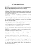
9 Flocculation provides slow mixing that leads to the formation of macro flocs, which then settles out in the clarifier zone. The settled solids primary sludge are pumped into sludge drying Plant Operation6. Aeration tank: The water is passed like a thin film over the different arrangements like staircase shape. Dosing of Urea and DAP is done. Water gets direct contact with the air to dissolve the oxygen into water. BOD & COD values of water is reduced up to 90%.7. Clarifier: The clarifier collects the biological sludge. The overflowed water is called as treated Effluent and disposed out. The outlet water quality is checked to be within the accepted limit as delineated in the norms of the Bureau of Indian standards.
10 Through pipelines, the treated water is disposed into the environment river water, barren land, Plant Operation8. Sludge thickener: The inlet water consists of 60% water + 40% solids. The Effluent is passed through the centrifuge. Due to centrifugal action, the solids and liquids are separated. The sludge thickener reduces the water content in the Effluent to 40% water + 60% solids. The Effluent is then reprocessed and the sludge collected at the Drying beds: Primary and secondary sludge is dried on the drying beds. FLOW CHART OF ETPI nfluentScreeningEqualization(Lime + Alum) pH = , TSS removal Disperse unitRECYCLETANKS edimentation tank{pH = } Sludge thickening unit Biological Treatment & Aeration{Dosing = (Urea + DAP) for O2}BOD removal ~ 90% COD removal ~ 90% SludgeSludge dischargeFish pond EffluentEffluent discharge60% water + 40% solids40% water + 60% solidsSCREENING Screeningisthefiltrationprocessforthesep arationofcoarseparticlesfrominfluent.