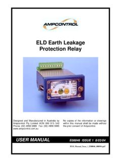
Transcription of ELD Earth Leakage Relay - Blue Electronics
1 ELDB001 18/11/02 CRN: 4818 AMPCONTROL CSM Pty Limited ACN 000 770 141 250 Macquarie Road Warners Bay NSW 2282 Phone: (02) 4956 5899 Fax: (02) 4956 5985 ELD Earth LeakageRelayDesigned & Approved to DescriptionThe Ampcontrol ELD Earth Leakage Relay is electronic indesign and is based on microprocessor technology. TheRelay uses a toroid to measure Earth fault current. Adefinite time operating characteristic is provided withadjustable trip sensitivity and time delay. When a faultoccurs and the trip level and time delay is exceeded therelay s trip function is activated, operating the trip contactsconnected in the system control circuit.
2 In Fail-Safe Modethe trip is latched in non-volatile memory and requiresoperation of the reset input to clear the trip condition. Aninternal reset is also provided on the facia of the ten-segment LED bar graph indicates the % of leakagelevel being detected. This reading can be remotelymonitored/displayed using the 4-20mA Output of theRelay. When the Relay measures currents with frequenciesmuch greater than 50Hz the bar graph LED fast flashes(5Hz) instead of being steady. Should the high frequencycurrent persist until the time delay is exceeded the relaywill trip and the LED (Harmonic Trip) will ELD Earth Leakage Relay is housed in a stainless steelcase and can be either DIN Rail mounted or PanelMounted through a 68 x 38mm cut out.
3 When panelmounted the front of the ELD Relay is designed to provideIP-56 ingress protection. It also provides provision toprevent unauthorised adjustment of the trip internal switch mode power supply allows the ELD tooperate from 24 VAC to 132 VAC or 20 VDC to Features Microprocessor based for high stability and accuracy. Adjustable trip level and time delay settings. Fail safe or non-fail safe on loss of supply. Bar graph to monitor Leakage level. 4-20mA Output forremote indication. Maximum Leakage since last power up/reset stored inmemory. Continual monitoring of the toroid. AC or DC Supply operation. Functions normally for a period of two (2) secondsduring extreme power dip or power loss.
4 Designed and tested to for use ApplicationTo ensure maximum protection the Earth Leakage systemshould be used in conjunction with the other protectionsystems covered by AS2081. The collective systems aredesigned to limit touch and step Relay is also suitable for industry where equipment orsystem Earth Leakage protection is required. The Relay is notsuitable for personal protection, users of portable drills,grinders etc, which require trip levels of 20-30mA, withinstantaneous operation. (Refer AS3190).The ELD Relay is designed for use on Earth ELD Relay continually monitors the toroid and if theconnection is lost the Relay will trip and flash the CT FaultLED.
5 Methods of Earth Leakage ProtectionThere are two methods of protection used. They are theCore Balance and Series Neutral Earth Leakage Balance:With this method the three phases are passedsymmetrically through the toroid. If there is no earthfault, the vector sum of the currents in a three-phasesupply is zero. If current from any phase flows to earththe system becomes unbalanced. The toroid produces anoutput, which trips the Neutral:With this method the neutral connection of the supplytransformer is passed through the toroid. An Earth faulton any of the phase conductors causes an Earth currentwhich returns, through the toroid, to the star point of thetransformer and trips the test current is injected through the window of the toroidto test the operation of the Relay (See typical connectiondiagram, page 2).
6 To reset the Relay press the button locatedon the facia of the Relay or provide an external normallyopen contact. The reset button is also used to access thememory of the processor to view the maximum level ofleakage since the previous trip. A section of the bar graphwill slow flash (2Hz) indicating the peak level while, thereset button is held closed and will continue to flash for 1second after the reset button is TECHNICAL INFORMATION3. 2 ToroidsThe ELD Relay is designed and recommended for use withAmpcontrol EL500S series Toroids. They are availablewith window sizes 60, 85, 112mm. These allow trip settingsfrom 100mA to Mode of OperationThe Relay can be operated in fail-safe or non-fail safemodes of Safe Mode:This mode is the default and preferred method, wherethe Relay drops out on fault or loss of power.
7 Power tothe Relay is from the line side of the isolating device orfrom an independent Fail Safe Mode:In this mode of operation the Relay picks up on method should only be used when the supply to therelay is only available from the load side of the isolatingdevice. To select this mode link the NFS :This mode of operation should only be used when thereis not a requirement to comply with SpecificationsRelay Supply Volts:24 132 VAC, 20-185 VDC4-20mA Output:The Loop Powered current output represents the leakagecurrent as a percentage of the trip => 0% Leakage , 20mA =>120% Leakage (100% = )Maximum Loop Resistance = [Vs-10] x 50, where Vs mustbe greater than 10 VDC and less than Contacts:1 N/O, 1 C/O.
8 Rated at 5A 250V, 100VA and Time Delay Settings:Two separate rotary, 16 position switches, set the trip andtime delay parameters of the relaySwitch PositionTrip Level mATime Delay mS01005011501002200150325020043002505350 3006400350745040085004509750500A1000750* B12501000*C15001500*D17502000*E20002500* F25003000*Values marked with an asterisk (*) should not be selectedwhen there is a requirement to comply with : 47 H x 77 W x 116 D mm5. Equipment ListE08405 ELD Earth Leakage RelayE08406 ELD DIN Rail Mounting KitE08554 ELD-ELC Adapter KitE08554 ELD-ELC/F Adapter KitC18058 Toroid - 60mm IDC18059 Toroid - 85mm IDC18057 Toroid 112mm IDTypical Connection Diagram