Transcription of Electric Motors and Drives - UFL MAE
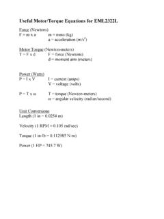
1 EML 2322L MAE Design and Manufacturing Laboratory Electric Motors and Drives To calculate the peak power and torque produced by an Electric motor , you will need to know the following: motor supply voltage: Vs [V] Peak motor current: Is [amps] motor velocity: N [rpm] The power produced by the motor can be calculated as: P [watts] = Vs [volts] Is [amps] (Eq. 1) Converting power to units of horsepower: P [hp] = P [watts] [hp/watt] (Eq. 2) Since power is equal to work divided by time, we can use the definition of horsepower to understand the useful torque produced by the motor : 1 [hp] = 750 [W] = 550 [lb-ft/s] = 33,000 [lb-ft/min] (Eq.)
2 3) Now let s select a real motor to work with from the motor Specifications link on the course website: We will select one of the DC right angle drive gear Motors used in the lab. 44 RPM 12/24 VDC 1/70 HP ENTSTORT GEARMOTOR 44 RPM at 12 VDC no load Voltage 12/24 DC Amps 1-1/2 full load Reversible Duty continuous Shaft 10 mm x 1 1/4" with 8 mm threaded end Mount 3 bolt on 2" Size 6 3/4" x 2 5/8" x 4" From the basic equations presented above: P = 12 V A = 18 W = hp Comparing this value to the rated power of the motor (1/70 = hp), we see the actual power produced is substantially less than the computed electrical power.
3 This loss is due to the electrical efficiency of the brushed-type motor . The electrical efficiency will be denoted by motor and for the purpose of this course, we will assume the following: motor 60% Now the power can be more accurately computed as follows: P = V I motor = 12 V A = W = hp Using the definition of hp (Eq. 3): hp = lb-ft /s = lb -in/s Therefore, this motor should be able to lift a lb load at the rate of 1 foot per second; this is equivalent to lifting a 1 lb load at feet per second. Note the difference is you trade torque for speed or vice versa. Looking at it in units of lb-in instead of lb-ft, this motor should be able to lift a 95 lb load at the rate of 1 inch per second; this is the same as lifting a 1 lb load at 95 inches per second.
4 Suppose we wish to calculate the velocity of our robot if we consider using these Motors to power the drive wheels. First, we need to select a wheel diameter. Returning to parts found in lab, let s arbitrarily select an 8 diameter wheel to get a baseline. The linear velocity can simply be calculated using the circumference of the wheel: V [in/min] = D [in/rev] N [rev/min] (Eq. 4) In the case of the example 44 rpm right angle drive gear motor and the 8 wheel, this equates to: Vno-load = ( 8 in)/rev 44 rev/min = 1105 in/min = 18 in/sec = ft/sec Note the 44 RPM speed rating of the motor is under no load.
5 Ideally, we would need to know the torque vs. speed characteristics of the motor to calculate the true shaft speed under the load ( weight) of moving the robot around. For a first approximation, let s take 75% of the no-load speed rating. Therefore our robot velocity is now reduced to V = .75 Vno-load = in/sec = ft/sec Referring back to a problem statement from a previous semester, the arena length is 20 feet, the buckets are placed about 2 feet from the end of the arena, the robot passes through a 6 foot long tunnel and the robot starts 5 feet from the tunnel entrance. In addition, the buckets appear to be located about 6 feet apart from each other.
6 Therefore, depending on your bucket collection strategy, you can approximate the distance traveled by the robot. The most direct path for collecting the two buckets would be approximately: d 2 (5 ft + 6 ft + 18 ft) + 6 ft + 2 ft (for backing up) 66 ft Now that we know the estimated distance and velocity, it s easy to calculate the estimated driving time (not including the time required to dump, sort and release the buckets): t = d / V = 66 ft / ft/sec 60 sec Before each group selects its final drive Motors , we want to see a similar time estimate computation. As an example of why we want to perform these simple calculations, suppose we ignore the suggestion to read the spec sheet for each motor before selecting one.
7 Instead, we choose one of the Globe DC inline gear Motors because of their impressive size and cool looks. Repeating the above calculations: RPM 12 VDC GLOBE GEARMOTOR Double reduction gear motor . Primary gear motor is removable from secondary reduction for use as a 25 RPM output. Ideal motor for robotics, rotary actuators, and other low speed DC applications. SPECIFICATIONS RPM: primary 25; secondary Voltage 12 DC Amps 130 mA no load Torque: primary 33 in-lb ; secondary 125 in-lb Ratio 620:1 Rotation reversible Duty continuous Mount primary 4 bolt on 1" BC secondary 5 bolt on 4 7/8" BC Notice the RPM specification on the secondary reduction of the motor /gearbox assembly: RPM.
8 This is approximately 10% of the speed rating of the first motor we looked at (44 RPM), so the robot velocity will be reduced 90%: Vno-load, GLOBE = ( 8 in)/rev rev/min in/sec = .15 ft/sec V GLOBE = .75 Vno-load, GEARMOTOR = in/sec = .1125 ft/sec Computing the time required to traverse the arena using the slower Globe gear motor : t = d / V = 66 ft / .1125 ft/sec 590 sec 10 min (!) Characterizing Motors Speed (rotational velocity), N [rev/min] or [rad/s] Angular acceleration, [rad/s2] Torque, T [lb-ft ] or [N-m] o T = F r o T = I Power P the rate at which work is done o P = T Electric Motors are characterized by torque vs.
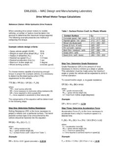
9 Speed curves, such as the following: 203040506070051015202530354045 Torque, T [lb-in]Speed, N [rpm]Torque vs Speed (Entstort motor ) You make use of the torque / speed curve as follows: 1. Calculate or measure the force required to propel the device. For example, let s assume 50 N force. 2. Calculate the torque needed as T = F r; assuming r = m: T = 50 N m = 5 N-m 3. Determine motor speed from torque curve. 4. Calculate new wheel speed using the actual motor shaft velocity from the torque vs. speed data (V = r ; V = D N ; etc.) A Closer Look at Calculating the Required Wheel motor Torque In the above example, for simplicity, I assumed a force of 50N was necessary to move the robot.
10 Now let s look at how to really calculate this number. To find the actual force, we need to measure or estimate the static friction coefficient between the floor and wheels, since that is what we are overcoming when we push the robot forward (assuming axle friction is negligible). If we look up this static friction coefficient (which is dependent on the two materials in contact, perhaps a concrete floor and a nylon wheel) and we know the weight on each wheel (W1, W2, etc), we can calculate the friction force as the static friction coefficient times the wheel weight for each wheel on the robot. If we sum these friction forces, then we know how much force is needed to overcome the static friction to get the robot rolling.