Transcription of ELECTRIC SLIDE-OUT SYSTEM OPERATIONS AND SERVICE …
1 ELECTRIC SLIDE-OUTSYSTEMOPERATIONSANDSERVICE MANUAL2 TABLE OF CONTENTS PAGE # OPERATIONS MANUAL .. 11. SYSTEM DESCRIPTION .. MAJOR COMPONENTS .. 12. HOW TO OPERATE YOUR SLIDEOUT SYSTEM .. WARNING .. EXTENDING THE ROOM .. RETRACTING THE ROOM .. 23. MANUALLY OVERRIDING YOUR SLIDEOUT SYSTEM .. 2-54. PREVENTATIVE MAINTENANCE .. 6 SERVICE MANUAL .. 71. SERVICE PARTS .. 8-102. REPLACEMENT kits .. MECHANICAL COMPONENTS .. ELECTRICAL COMPONENTS .. GEARMOTORS .. 163. TROUBLESHOOTING THE SLIDEOUT SYSTEM .. 17-184. COMPONENT PART REPLACEMENT INSTRUCTIONS .. GEARMOTOR .. RELAY CONTROL .. CIRCUIT BREAKER .. CURRENT LIMITER CONTROL .. SPUR GEAR SHEAR PIN.
2 SPUR GEAR .. DRIVE SHAFT .. MANUAL OVERRIDE GEARBOX (OPTION) .. SLEEVE BEARINGS .. INNER RAIL ASSEMBLY .. 235. REQUIRED INFORMATION FOR ORDERING PARTS .. 24 APPENDIX .. 25-32 WARRANTY .. 333 OPERATIONS MANUALThe power Gear ELECTRIC slideout SYSTEM in your unit is designed to give you years oftrouble free operation and reflects the latest state of the art technology. READ,STUDY, AND UNDERSTAND THIS MANUAL BEFORE OPERATING THISSLIDEOUT SYSTEM DESCRIPTIONYour power Gear Slideout SYSTEM is a rack and pinion design operated by a 12 Volt DCelectric MAJOR COMPONENTS Inner rail assemblies are designed to support the room weight. The 12 Volt DC gearmotor will operate the room using power from the on-board unit battery. Slideout systems are equipped with a manual override that allows you toextend / retract the room in the event of a loss of power .
3 A specially designed control that gives the user full control of roommovement, in or out. The control has a load sensing capability that stops themotor when the room is fully extended or HOW TO OPERATE YOUR SLIDEOUT WARNING ALWAYS MAKE SURE THAT THE SLIDEOUT ROOM PATH IS CLEAR OFPEOPLE AND OBJECTS BEFORE AND DURING OPERATION OF THESLIDEOUT ROOM. ALWAYS KEEP AWAY FROM THE SLIDE RAILS WHEN THEROOM IS BEING OPERATED. THE GEAR ASSEMBLY MAY PINCHOR CATCH ON LOOSE CLOTHING CAUSING PERSONAL INJURY. INSTALL TRANSIT BARS (IF SO EQUIPPED) ON THE SLIDEOUTROOM DURING STORAGE AND TO FOLLOW THESE INSTRUCTIONS COULDRESULT IN SERIOUS INJURY OR EXTENDING THE ROOM1. Level the Verify the battery is fully charged and hooked-up to the electrical Remove the transit bars (if so equipped).4. Turn ON the on/off switch or key (if so equipped).
4 5. Press and hold the IN/OUT switch (Fig. 1) in the OUT position until the roomis fully extended and stops Release the switch, which will lock the room into position. NOTE: If theslideout switch is held after the room in fully extended, the control will sensethat the room has stopped and will shut off the motor after a few Turn OFF the on/off switch or key (if so equipped). RETRACTING THE ROOM1. Verify the battery is fully charged and hooked-up to the electrical Turn ON the on/off switch or key (if so equipped).3. Press and hold the IN/OUT switch (Fig. 1) in the IN position until the room isfully retracted and stops Release the switch, which will lock the room into position. NOTE: If theslideout switch is held after the room in fully retracted, the control will sensethat the room has stopped and will shut off the motor after a few Turn OFF the on/off switch or key (if so equipped).
5 6. Install the transit bars (if so equipped).Fig. 1 Slideout Switch53. MANUALLY OVERRIDING YOUR SLIDEOUT SYSTEMYour power Gear slideout SYSTEM is equipped with a manual override that allows you toextend or retract the room in the event of a loss of : If the room does not move when the switch is pressed, check thefollowing: make sure the slideout SYSTEM is turned on battery is fully charged and connected the transit bars are removed (if so equipped). After the previous items have been checked and the room still does not move whenthe slideout switch is pressed, follow these simple steps to manually override yourslideout Turn OFF the on/off switch or key (if so equipped). NOTE: The override will notwork if the switch is turned Locate the slideout electrical controller (refer to your dealer or RV manufacturer forlocation).
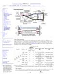
6 There are (2) versions of the controller (Fig. 2). For version 1, unplug the(6) pin wiring harness from the controller. For version 2, remove one of the motorleads, either the motor I or motor II lead from the Locate the slideout motor (Fig. 4). It will be mounted to one of the slideout : If the RV has an underbelly or a cover over the motor, these parts must beremoved to access the Rotate the brake lever, on the backside of the motor, counter-clockwise (looking fromthe rear of the motor) about 1/8 of a turn to the released position. Refer to Fig. will release the brake that holds the room in Locate the manual override for the slideout SYSTEM . Refer to Fig. The room is now free to move. Using either a 5/8 or 3/4 wrench or socket, crankthe room either in or out completely (depending on your needs). NOTE: If theslideout SYSTEM is supplied with a gearbox override (optional), use the crank handleto move the When the room is fully in (or out) apply pressure to the wrench/ratchet and return thebrake lever to its engaged position.
7 This will ensure the room is locked into a Install the transit bars to the slideout room (if so equipped) and take the unit to anauthorized dealer for SERVICE .!!! WARNING !!!WHEN THE MOTOR BRAKE IS DISENGAGED THE SLIDEOUT ROOM WILL NOTLOCK INTO PLACE; THEREFORE, THE ROOM WILL NOT BE SEALED. WHEN THEROOM HAS BEEN MANUALLY RETRACTED, BE SURE TO INSTALL THE TRANSITBARS (IF SO EQUIPPED) AND RETURN THE MOTOR BRAKE LEVER TO ITSNORMAL ENGAGED POSITION IN ORDER TO SEAL AND LOCK THE ROOM 3 Motor Brake Lever910 Fig. 4 Motor and Manual Override General Location4. PREVENTATIVE MAINTENANCE11 Your power Gear slideout SYSTEM has been designed to require very little ensure the long life of your slideout SYSTEM , read and follow these few : DO NOT WORK ON YOUR SLIDEOUT SYSTEM UNLESS THE BATTERYIS DISCONNECTED. When the room is out, visually inspect the inner slide rail assemblies.
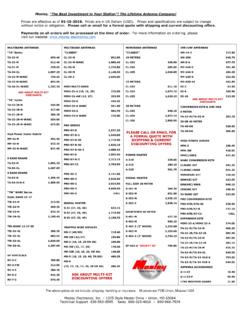
8 Refer to Fig. 4for location of inner rail assemblies. Check for excess build-up of dirt or other foreignmaterial; remove any debris that may be present. If the SYSTEM squeaks or makes any noises it is permissible to apply a coat of lightweight oil to the drive shaft and roller areas but, remove any excess oil so dirt anddebris do not build-up. DO NOT use YOU HAVE ANY PROBLEMS OR QUESTIONS CONSULT YOUR LOCALAUTHORIZED DEALER OR CALL US AT power GEAR (800-334-4712).12 SERVICE MANUAL!!! CAUTION !!!THE FOLLOWING INFORMATION IS FOR AUTHORIZEDRV DEALERS AND SERVICE OWNERS SHOULD NOT ATTEMPT THESE REPAIRSOR OTHER THAN A RV AUTHORIZED SERVICETECHNICIAN ATTEMPTING REPAIRS WILL VOIDWARRANTY.!!! CAUTION !!!131. power GEAR SLIDEOUT SYSTEM REPLACEMENT MECHANICAL COMPONENTSKIT P/NDESCRIPTION522505 KIT, SHAFT, LP3 ITEM # PART # DESCRIPTION QUANTITY PER KIT 1 18-1036 PIN ROLL.
9 140 2 2 510036 BEARING SLEEVE .75 2 3 521336 KEY WOODRUFF #606 1 4 521656 SHAFT DRIVE IDLER ASSY 1 5 521668 GEAR SPUR ASSEMBLY 1 6 530042 ROLLER, IN. KIT FOR THE FOLLOWING SYSTEMS: 521243 521777 532062 532064 532068 P/NDESCRIPTION532023 KIT, ROLLER, INNER, LP3 ITEM # PART # DESCRIPTION QUANTITY PER KIT 1 520011 ROLLER INNER 3X3 2 2 530045 SPACER, INNER BEAM, .5 IN3 3 532022 SPINDLE,INNER RAIL1520011532022530045123 REPLACEMENT KIT FOR THE FOLLOWING SYSTEMS: 521267 - P/NDESCRIPTION520258-DRIVE SIDEHEX SHAFT REPLACEMENT KIT 520259-IDLER SIDE(DOUBLE RAIL SLIDEOUT SYSTEM ) ITEM # PART#DESCRIPTION QUANTITY PER KIT 1 18-1032 Cotter Hairpin2 2 510036 Sleeve Bearing2 3 18-10391/4 Coiled Pin1 4 510104 Spur Gear1 5 520224 Hex Coupling Shaft (520259 only)1 6 15-1343 Screw, HHC, 1/4-20 x 2 1 7 16-10371/4 Washer4 8 15-1006 Hex Lock Nut, 1/4-201 9 18-10369/64 Roll Pin-(520258 only)1 10 520039 Drive Shaft Assembly-(520258 only) 1 51003618-103951010452022415-134315-10061 6-10371234567818-10369 REPLACEMENT KIT FOR THE FOLLOWING SYSTEMS.
10 521267 532003 522559(idler) 522666(idler only) 521363( idler only) 521773(idleronly) 521776(idler only) 521866(idler only) 521994(idler only) 522267(idler only) 522412(idler only) 522450(idler only) 523170(idleronly) 523291(idler only) 521605(idler only) 521604(idler only) 520222(drive only)16 KIT P/NDESCRIPTION520717 GEAR SHAFT REPLACEMENT KIT(SINGLE RAIL SLIDEOUT SYSTEM )ITEM # PART # DESCRIPTION QUANTITY PER KIT 1 5202233/4 Hex Coupling Override1 2 18-1036 9/64 Roll Pin1 3 18-1032 Cotter Hairpin1 4 510036 Sleeve Bearing2 5 18-1039 1/4 Coiled Pin1 6 510104 Spur Gear1 7 520039 Motor / Coupling Shaft 8 18-10071/4 Roll Pin118-100718-103618-1039510036510104520 22352003912345678 REPLACEMENT KIT FOR THE FOLLOWING SYSTEMS.