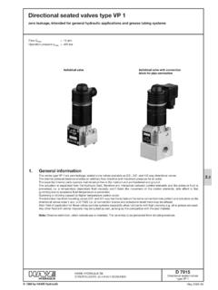
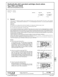
Transcription of Electro-hydraulic pressure switches type DG
1 Electro-hydraulic pressure switches type DGD 5440 pressure switches type 2004-01 HAWE HYDRAULIK GMBH & CO. KGSTREITFELDSTR. 25 81673 M NCHEN4 1973 by HAWE informationElectro- hydraulic pressure switches are devices which close or open elec-trical contacts when pressurized (DIN ISO 1219-1). They are usually used forall applications where a electrical signal should be triggered whenever theset pressure is achieved or exceeded. This signal may be utilized to start asubsequent operation cycle (operation of a solenoid actuated directionalvalve) or to stop an operation cycle (cut-off of the pump drive, idle positionof a solenoid actuated directional valve).TypeDG 1 ..DG 8 (F)Type DG 3 .. pressure pmax= 700 barSee also:For electronic pressure switches type DG 5 Esee D 5440 EAnalogous pressure transducer type DT 1see D 5440 TAnalogous pressure transducer type DT 2see D 5440 versions, main dataCodingElectrical connectionInsidethe device(Pg 9)Devicesocket DIN 43650(ISO 4400)DG 1 RDG 1 RFDG 1 RSDG 1 R FSDG 8DG 8 FOperationpressure range pmin2).
2 Pmax(bar)20 .. 600(main switch)20 .. 180(ancillary switch)Pressureresistantup to (bar) 3) 600600700 Symbol20 .. 600200 .. 700100 .. 40020 .. 2504 .. 124 .. 5012 .. 170 DG 33DG 34DG 35DG 36 1)DG 364DG 365 2) pminrepresents the lowest guideline pressure figure where thepressure switch is recommended. The operation hysteresis willincrease dramatically below this figure3) Independent of the selected operation point1) For applications where exceeding of or returning intoa lowest pressure range should be signaled. Not ide-ally suited for operation commands acc. to sect. 1, dueto a bad hysteresis (see page 2).Order examples:Table 1:Basic typeTable 2: hydraulic connectionCodingno codingno coding- 1/4- Y1- Y2- Y3- YS 6- YS 8- Y6- Y8 Connection modeDirect via pipe fittings shapeB conf. DIN 3852 page thread G 1/4 DIN ISO228/1 (BSPP)Clamping nut DIN 16283( pressure gauge fitting, 16270)with fittings acc.
3 To D 7065 Basic version for sub-platemountingSub-plate G 1/4 Tapped journal G 1/4 ATapped journal M12x1,5 Tapped journal G 1/8 Tapered journal #6 and #8 for progressive ring andsleeve nutPipe #6 and #8 designedfor pipe fittingsDG1R FDG 33-YS 8DG 34 VVersionTurn knob atDG 1R(S), DG 1 RF(S)DG 8 (F) for main switch + set screw for ancillary switchSet screw at DG DG :Manually adjustable (Wing screw and wing nut)only DG :Turn knobonly DG :Lockable turn knob (BKS-lock)Suited for keys conforming to the standards of the motor industry. Key is not scope of delivery (Key is only in the possession of the authorized operators).F= Version with bezelfor switch boardinstallationSuitedforDG 1 8 (F)DG 3:Means of adjustmentCodingno coding(stan-dard)RVHFor combination with various connec-tors, see D 7065D 5440 page and hydraulicAdjustmentSwitch pressurePressure risesPressure dropsThe figures in the table representonly guideline figures.
4 The exact operation point must be detected with a pressure gauge !The pump might after-run due to mass-effect, at appli-cations where the pump is directly 1 turn knob at the dial (slight deviations between scale reading and pressure gaugereading are 8 (F)Main switch via turn knob at the dial (like DG 1 )Ancillary switch via set screw (a/f 8) afterslackening the lock nut. Each turn ,50 response pressure may be set eitherlower or max. even to the set pressure ofthe main switch (max. 180 bar).Application example: Disconnecting a con-trol circuit which is no longer required oncethe preset "ancillary" pressure is exceededwithin the successive operation cycleDG set screw after loosening the lock-nut(a/f 10)DG via winged set screw, after loos-ening the winged lock-nutDG via turn knobDG via turn knob, after opening thelock (key)The hysteresis curves belowshow the trigger deviations tobe expected between uppertrigger pressure pofor pressurerise and lower trigger pressurefor pressure calculated pressure figure is to be regardedonly as a rough trigger point, where the switchchanges from idle into working position(Response pressure , adjustment pmax, see , table 1)pu=Lower trigger point, where the switch returns from working into idle set pressure acc.)
5 To sect. 2, table 1oupkp = pressure setting (bar)Adjustment length s (mm)maxoppDesignSurface protection ofall steel partsInstalled positionMass (weight)TemperaturePressure fluidSpring loaded piston type pressure switch, zero leakageDG 1 and DG 8 (F)= Switch housing zinc galvanizedDG TuffridedDG 1 and DG 8 (F)= Standing, dial sideways, hydraulic part downwardsDG AnyDG 1 kgDG 33 to 365= kgDG 8 (F)= kgDG kgDG kgAmbient: approx. +80 CFluid: +80 C, pay attention to the viscosity range! Start temperature down to -40 C are allowable (Pay attention to the viscosity range during start!), as long as the operation temperature during consequent running is at least 20K (Kelvin) pressure fluids: Pay attention to manufacturer's information. With regard to the compatibility with sealing materials do not exceed +70 :Type DG 35 also suitable for cold-storage depot applications (permanent sub 0 C), coding DG 35 KBHydraulic fluid acc.
6 To DIN 51524 table 1 to 3; ISO VG 10 to 68 acc. to DIN 51519 Viscosity range: min. approx. 4; max. approx. 1500 mm2/secOptimal operation range: approx. mm2/secAlso suitable are biologically degradable pressure fluids of the type HEPG (Polyalkylenglycol) andHEES (synth. Ester) at operation temperatures up to approx. +70 response pressurek ( - );DG 33, DG 34<DG 35, DG 364, DG 365=DG 36D 5440 page dataProtection classDG 1 Rand DG 8(F)= IP 54DG IP 65(DG = IP 67)Operations/h 1)Guideline figure max. 2000 operations/h (rather evenly distributed). Observe the max. number of operation cycles (see curve below). Tigger accuracy *2 .. 3% (Repeatability during pressure rise!)Connection 1)DG 1R(F):via cable gland Pg that the leads are properly routedin the switch cavity (high-flex line ).An assembly manual is scope of deliverywith every S +Resting positionResting positionWorking positionWorking positionRear view(removedcover)DG 8(F)DG ) Figures also apply to DG acc.
7 To sect. 5DG with electric connection M 12x1 (conforming DESINA)Order coding:DG 34 M possiblyoff-set by 3 x 90 Basic typeDG 3 acc. to table 1 Electrical connection M 12x1 Means of adjustmentand hydraulic connectionacc. to table 3 and 2 Supply voltage:U = 24 V DC ( V DC conf. EN 61121-2)Max. switched current:Imax= 2 ADG for quarter-turn plugOrder coding:DG 33 S typeDG 3 acc. to table 1 Electrical connection for quarter-turn plugMeans of adjustmentand hydraulic connectionacc. to table 3 and 2 Plug:For quarter-turn PA 6, Co. SchlemmerAngled plug 7846 010 AStraight plug 7846 010 BPlug connection 1)DG , DG 8(F) and DG via 3-pin inline socket A DIN 43650 (ISO 4400).Numbering of the plug lugs beneath over-laid rubber plugs are scope of delivery with DG8(F), see dimensional 5440 page 4 Continuation of sect. Electrical dataUtilized Co.
8 SAIA Burgess, microswitchD-26127 OldenburgPressure switchMicroswitch typeMechanical service life servicelife approx. opera-tion cyclesDG X 04-Z 2510 x 1061 x 106DG 8 (F)XFB 7-S 730 x x 106DG NT 710 x x 106with 12V DC = 4 A and L/R = 10 msat 230V AC, 1 A and cos. = performanceVDE 0630 A/VDC-operation performanceObserve the min. current rating to ensure flawlesss operation:24V DC = Imin= 10 mA12V DC = Imin= 100 mA3/3802/2501/250 Operation cyclesCurrent (A) at 230V ACDC-voltage (V DC)Current (A)1)1)1)1) Figures also apply to DG acc. to sect. 5D 5440 page 51) Attention: This dimension dependson the manufacturer and may be mm acc. to DIN EN 175301-803(DIN 43650)!2) Applies also to type DG acc. tosect. dimensionsAll dimensions in mm, subject to change without notice!EarthingterminalCable glandPg 9 Suited for pipe fit-tings with tappedjournal shape BDIN 3852, sheet 2 Type DG 1 RType DG 1 RFwith bezel for switch board installationInstallation aperture #100(sheet thicknessmax.
9 5mm)ActuationcylinderFor missing dimen-sions see DG 1R !For missing dimensionssee DG 1R or DG 1RF!Type DG 1RS, DG 1 RFS and DG 8(F)Plug may be installedrotated by 4x90 , cable gland Pg 9 Set screwfor ancillary switchwith DG 8(F)Turn-knob for mainswitch, max. figurewith DG 8(F)Circuitry of themain switchCircuitry of the an-cillary switch (onlywith DG 8(F)) hydraulic port 2) Suited for typeDG 1R(F)DG 1R(F)SThread G*1/4 forpipe fittingsThread G*1/2 for connecting apressure gaugeSeal ring Cu DIN 7603 Thread G*1/2 fittingtype X1 (example),see can be turnedand fixed in any directionG*1/4 Attention:The dial housing must notbe rotated in relation tothe hexagon (a/f 27) dueto functional reasons!approx. 140approx. 50a/f 27a/f 32G* = (BSPP)G* 1/2AG*1/4D 5440 page 6 Type DG (means of adjustment without coding)Type DG DG of adjustment coding VMeans of adjustment coding HPlug may be installedrotated by 4x90 , cable gland Pg 9 Set screw a/f 10and lock nutHydraulicconnectionM4, 6 deep, core hole 9 deep1) Attention: This dimension depends on themanufacturer and may be max.
10 40 mmacc. to DIN EN 175301-803 (DIN 43650)!DG - Y1 (G*1/4)DG - Y2 (M12x1,5)DG - Y3(G*1/8) Tapped journal with sealing edgeDG - YS 6DG - YS 8 Pipe connectionwith EO-progressivering and sleeve - - Y8 Pipe endClampingplateThru-hole DG may be installed facing in any direction after slackening boltsM4 of the clamping of adjustment coding RWing screwWing nutHydraulical connection suited for DG pattern for base plate(top view)For missingdimensionssee below!Sealing via if required as a complete seal kit:DS 5440-33 (DG 33)DS 5440-34 (DG 34)DS 5440-35 (DG 35)DS 5440-36 (DG 36, DG 365)Indicator ring(yellow)Quarter-turn PA 6,(Co. Schlemmer)approx. 75approx. 35approx. 1)G* = (BSPP)G*1 (Y3)Turn knobTurn knobD 5440 page 7DG 20 MDG 2 MDG 2 HDG 24 HDG 20 MSDG 2 MSDG 2 HSDG 24 HS10 .. 7040 .. 160100 .. 500400 .. DG (run-discontinued model)Order example:DG 2 H - X1 TypeDG pattern symbolTable 4: Basic type and main dataCodingElectrical connectionHydraulic liketype DG 1.