Transcription of Electromagnetic Compatibility (EMC) - AMV …
1 Directives & StandardsTechnical InformationEMCE dition 5 aim of Electromagnetic Compatibility considerations isto avoid or minimize the influence of Electromagnetic phe-nomena on a device, equipment or system and on living orinert matter. To achieve this, methods of measurement andtest, as well as limits and levels of Electromagnetic emis-sion and of Electromagnetic immunity are defined in a largenumber of EMC 1: Generic EMC Emission Standards (only parts relevant to power supplies)IEC 61000-6-3/EN 50081-1:IEC 61000-6-4/EN 50081-2: Electromagnetic Compatibility Generic standards Electromagnetic Compatibility Generic standards Emission standard for residential, commercial andEmission standard for industrial environmentslight-industrial environmentsPortReferencedFrequency range andReferencedFrequency range and required limitbasic standardrequired limitbasic standardCaseCISPR 22 MHz, class BCISPR 11 MHz, Group 1, class A(radiated)EN 55022EN 55011AC MHz, class MHz, Group 1, class A(conducted)IEC 61000-3-2 kHzEN 60555-2 IEC 61000-3-3 kHzEN 60555-3 Electromagnetic Compatibility (EMC)Generic EMC StandardsGeneric EMC Standards specify requirements for productsand systems operating in residential or industrial environ-ments.
2 They apply to products for which no dedicated Prod-uct Family EMC Standards or Product EMC Standards of EMC PublicationsEMC publications and standards, developed by the IECand other standardization bodies, can be divided into fourgeneral categories:Generic EMC Standards, Basic EMC Publications, Productfamily EMC Standards and Product EMC Standards. Theseterms are defined in the corresponding chapters : The European EMC Directive does not cover the in-teraction between technical apparatus and the and Product Family EMC Standards take prec-edence over Generic EMC Standards and Product EMCS tandards take precedence over Product Family distinction between these four types of EMC publica-tions is not yet consequently applied within the IEC, CISPRand Cenelec (EN).Generic EMC Standards can be considered to be generalProduct Standards in that they specify a limited number ofessential emission and immunity tests, maximum emissionlevels as well as minimum immunity test levels with as-signed performance criteria but refer to the Basic EMCS tandards for detailed measurement and test & StandardsTechnical InformationEMCE dition 5 2: Generic EMC Immunity Standards (only parts relevant to power supplies)Referenced BasicPortRequirements of Generic StandardRequirements of Generic StandardPerformancestandardEN 50082-1 (IEC 61000-6-1):IEC 61000-6-2/EN 50082-2.
3 CriterionElectromagnetic compatibilityElectromagnetic Compatibility Generic standards Immunity Generic standards Immunitystandard for residential, commercialstandard for industrial environmentsand light-industrial environmentsIEC/EN 61000-4-2:Enclosure 4 kV contact discharge 4 kV contact dischargeBElectrostatic discharge (case) 8 kV air discharge 8 kV air dischargeIEC/EN 61000-4-3/Enclosure3 V/m,10 V/m,AENV 50204:(case) MHz, AM 80 %, 1 kHz, MHz, AM 80 %, 1 kHz, Electromagnetic field900 MHz, PM 200 Hz 1900 MHz, PM 200 Hz 1 IEC/EN 61000-4-4:Signal and kV, 5 kHz, capacitive clamp 1 kV, 5 kHz, capacitive clampBFast transients (burst)control(only if cables are longer than 3 m)(only if cables are longer than 3 m), 2 kV, 5 kHz, capacitive clamp(only for process control andaccording to EN)DC input and kV, 5 kHz, direct injection 2 kV, 5 kHz, direct injectionoutput(only if cables are longer than 10 m)AC input and 1 kV, 5 kHzoutputIEC/EN 61000-4-5:DC input kV line to earth, kV line to earth,Surges(and output) kV line to line kV line to lineAC input 2 kV line to earth, 4 kV line to earth, 1 kV line to line 2 kV line to lineIEC/EN 61000-4-6.
4 Signal and3 V,10 V,ACommon modecontrol MHz, AM 80%, 1 MHz, AM 80 %, 1 kHzconductedDC input(only if cables are longer than 3 m)(according to IEC only if cablesdisturbancesand outputare longer than 3 m)AC input3 V,10 V,and MHz, AM 80%, 1 MHz, AM 80 %, 1 kHzIEC/EN 61000-4-11:AC input30 %, 10 ms30%, periodsBVoltage dips60 %, 100 ms60%, 5 and 50 periodsCIEC/EN 61000-4-11:>95%, 5000 ms>95%, 250 periodsVoltage interruptions1900 MHz is referenced in EN standards EMC PublicationsBasic EMC Publications specify the general and fundamen-tal conditions and rules as well as the measurement andtesting techniques for the verification of EMC and serve asreference documents for the product committees of thestandardization bodies. Basic EMC Publications relate togeneral information, to the disturbing phenomena and tomeasurement or testing EMC Publications are general standards or technicalreports and are not dedicated to specific product families orproducts.
5 They should not include prescribed limits and re-lated performances. These are covered by the Generic,Product Family or Product & StandardsTechnical InformationEMCE dition 5 Emission StandardsElectromagnetic emission is the phenomenon by whichelectromagnetic energy emanates from a Frequency EmissionRadio frequency emission, also called radio frequency in-terference (RFI) is an Electromagnetic disturbance which isgenerated by electrical apparatus and can be received byother power supplies, the RFI is generated by the switchingdevices. The steeper the voltage steps and the higher theswitching frequency, the greater the high frequency contentof generated disturbances. These disturbances can coupleto other components in the power supply, producing noisesources radiating over a broad frequency 3 Disturbance power limits (quasi-peak) according toCISPR 14/EN 55014 Fig.
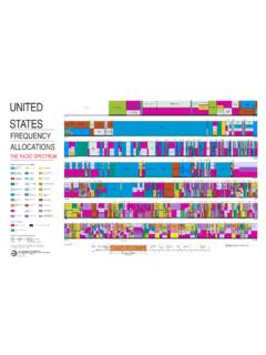
6 2 Disturbance field strength limits (quasi-peak) according toCISPR 11/EN 55011 and CISPR 22/EN 55022, normal-ized to a distance of 10 m806040200f [MHz]P [dBpW]5010015020025030007107 International basic emission standards are prepared by theCISPR (Comit international sp cial des perturbationsradio lectriques International special committee on radiointerference) and adopted by national or multinational is usual to measure disturbances at low frequencies(150 kHz up to approx. 30 MHz) as voltages between thesupply lines and earth (conducted disturbances) and athigher frequencies (above approx. 30 MHz) as fieldstrength or power (radiated disturbances).The graphs below provide an overview of the most commoninternational standards for both conducted and 1 Disturbance voltage limits (quasi-peak) according toCISPR 11/EN 55011 and CISPR 22/EN 25102030u [dB V]f [MHz] [dB V/m]f [MHz]AB07106 CISPR 11/EN 55011: Industrial, scientific and medical(ISM) radio-frequency equipment Electromagnetic distur-bance characteristics Limits and methods of measure-mentCISPR 14/EN 55014 (= VDE 0875, part 14).
7 Limits andmethods of measurement of radio disturbance characteris-tics of electric motor-operated and thermal appliances forhousehold and similar purposes, electric tools and similarelectric apparatusThis standard is not directly applicable to power supplies,but describes methods of measuring radiated electromag-netic power using an absorbing (MDS) clamp. The clampallows the simple measurement over a cable of a 22/EN 55022 (= VDE 0878, part 22; correspondsto FCC, part 15): Limits and methods of measurement ofradio disturbance characteristics of information technology(IT) equipmentMIL-STD-461C: Electromagnetic emission and susceptibil-ity requirements for the control of Electromagnetic interfer-enceDirectives & StandardsTechnical InformationEMCE dition 5 Current EmissionElectrical and electronic equipment inject harmonic cur-rents into their AC supply system.
8 In order to ensure elec-tromagnetic Compatibility , maximum harmonic disturbancelevels have been defined in the corresponding jjjjjFor undistorted, sinusoidal waveforms cos j is the dis-placement factor of the load current compared to the mainsvoltage (fig. cos j).For this special case j is also equal to the phase differencebetween true power and the apparent power:S = Urms IrmsTrue power:P = Urms Irms cos j = S cos jReactive power:Q = Urms Irms sin jApparent power is the vector sum of the true and reactivepower (fig. AC-power components).Harmonic DistortionFor nonlinear loads (for example rectifier) the load currentwill not be sinusoidal anymore (fig. Harmonic distortion).UItj = w0tt013004 Fig. 4cos jTrue PowerPReactive PowerQApparent PowerS13005 Fig. 5AC-power componentsUIt13006 Fig. 6 Harmonic distortionSince true power only takes place at the fundamental fre-quency (frequency of mains voltage), the analysis of thecurrent into fundamental and harmonic currents has to becalculated (Fourier analysis):I (t) = I0 sin ( 0t + j0) + I1 sin ( 0t + ji) +.
9 + In sin ( nt + jn)I0:amplitude of fundamentalIi:i = of ith harmonic 0 = 2 f0f0 = 50/60 Hz frequency of fundamental i = i 0i = of ith harmonicj0phase shift of fundamentaljii = shift of ith harmonicBased on this decomposition the Distortion Factor can becalculated:Contents of harmonicsK = rms-value Ii2i = 1K = Ii2i = 0 Power FactorFor single phase systems the power factor is defined as theratio of the true power delivered to the load to the apparentpower. Power factor is the generalized case of cos j, sincethe waveforms do not have to be sinusoidal. For the specialcase where the waveforms are sinusoidal, the power factoris equal to cos powerPPF = = Apparent powerSIn practice the mains voltage can be assumed to be sinus-oidal. So the power factor only depends on the distortion ofthe load current: The more the waveform is distorted, thelower the power factor.
10 A perfect power factor would beequal to 1, whereas the worst case power factor is cos j0PF = IrmsI0:Fundamental of load currentcos j0: Displacement factor of fundamental of load currentIrms:rms-value of load currentDirectives & StandardsTechnical InformationEMCE dition 5 orderMaximum permissibleharmonic currentABalanced three-phase all other equipment, included in one of tools Limits of class A, multiplied by equipment22% of input current at the510fundamental (odd only)3330 l %; l = circuit power factorDEquipment having an input a "special wave shape" (as defined in the standard) active input power W up to 600 (odd only) 61000-3-2: Limits for harmonic current emissions(equipment input current 16 A per phase)This standard deals with the limitation of harmonic currentsinjected into the public supply systems with nominal volt-ages of 220 V (line to neutral) or more.