Transcription of Electromagnetic Interference/Compatibility (EMI/EMC ...
1 Electromagnetic Interference/Compatibility (EMI/EMC) Control Test and Measurement Facility User Test Planning Guide National Aeronautics and Space Administration Lyndon B. Johnson Space Center Houston, Texas 77058 2 Table of Contents Electromagnetic Interference/Compatibility Test Facility ..3 Facility Layout ..4 Safety and Health ..6 Test Process Flow ..6 Proprietary Information ..7 Test Initiation Phase ..8 Test Request .. 8 Schedule and Cost Estimate .. 9 Test Preparation Phase ..9 Test Requirements .. 10 Test Article Documentation .. 10 Test Plan .. 11 Test Schedule .. 11 Test Article Delivery .. 11 Test Readiness Review .. 11 Test Execution Phase .. 12 Test Authority .. 12 Test Deviations .. 12 Test Closeout Phase .. 13 Customer Feedback .. 13 Facility Access .. 14 Roles and Responsibilities .. 15 Acronyms.
2 17 Appendices .. 18 Appendix A Facility Interfaces .. 19 Appendix B Test Request Worksheet .. 23 Appendix C Facility Specifications .. 28 Appendix D Facility Equipment .. 29 Appendix E Sample Test Configurations .. 32 3 Electromagnetic Interference/Compatibility Test Facility The Electromagnetic interference / Electromagnetic compatibility (EMI/EMC) Control Test and Measurement Facility supports engineering development and EMI/EMC measurements and provides EMI/EMC evaluation and certification testing of crew, flight, and ground support equipment including, but not limited to, Communication, Instrumentation, Biomedical, Guidance and Navigation, Computation, and Robotics. Services Provided Testing - developmental, engineering support, performance and precertification evaluation, and certification testing Conducted and radiated emissions and susceptibility testing ( , MIL-STD-461, all revisions.)
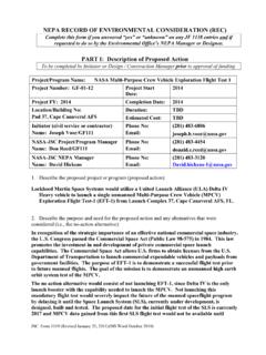
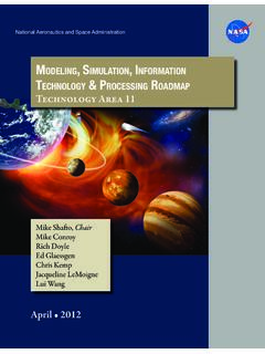
3 RTCA/DO-160, sections 16 through 21) Lightning indirect effects and Electrostatic Discharge (ESD) assessment ( , RTCA/DO-160, sections 22 and 25) Cable transfer impedance and equipment shielding effectiveness assessment EMC design consultation Detailed test planning support and test data collection/reporting Capabilities Shielded room enclosures Meet military standard MIL-STD-285 Synthesized signal generators Capable of covering a frequency range of 10 Hz to 26 GHz Radio frequency (RF) power amplifiers Provide up to 500 W of output power in the frequency range of 10 kHz to 18 GHz Lightning transient generator and support probes Provide test waveforms 1, 3A, 3B, 4, and 5A for lightning indirect effects testing up to Level 3 ESD test equipment Provides standard ESD test waveforms up to a 30 kV peak pulse voltage Complete line of general purpose ancillary test equipment Power supplies, oscilloscopes, power meters, and voltmeters High-fidelity EMC modeling software General purpose three-dimensional Electromagnetic modeling Point of Contact Lab Manager, Richard Deppisch Johnson Space Center 2101 NASA Parkway, Houston, TX 77058 (281) 483-0475 4 Facility Layout The facility has two shielded enclosures, or chambers, as shown in the accompanying figures.
4 The primary chamber is designed to accommodate larger pieces of equipment. The wall, ceiling, and floor are constructed of panels of 24-gauge galvanized steel sheets laminated to both sides of a -inch structural core. The floors are covered with tile and are designed to handle a loading capacity of 1,000 lb. per square foot. Each chamber is equipped with a 9 W x 3 D ground plane bench, covered with a copper sheet that is electrically bonded to the adjacent wall. The test benches stand 30 inches above the floor. KEYD oorsA -Sgl., 3 6 w X 7 6 h, lipB Dbl., 8 w X 10 h, lipC Sgl., 3 6 w X 7 6 h, lipHB 13 w X 20 hIP_A, IP_B & IP_C 2 IDIP_D 4 ID35 8 1000 ATest X23 X10 1000OH DoorControl X12 X10 Support X11 X10 Ladder up to 2P2To 102010RM10 RWBAC3 x5 table2 6 x5 tableEMI 8 8 9 13 1000BA2 6 x5 table57 23 28 3 6 3 4 9 4 34 8 IP_AIP_BIP_CIP_DNOTE: The walls and ceiling of the test room are treated with ferrite tiles and absorber material out to the dotted line and across the back wall.
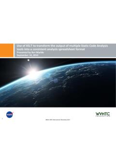
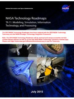
5 Test Bench can be removed or another may be added as needed to accommodate benchAbsorber Material Physical Layout of EMI/EMC Primary Facility in B14A/R1000 High Bay 5 Large Equipment Under Test (EUT) can be accommodated in the primary chamber via the 13 -wide rollup High Bay door in Johnson Space Center (JSC) Building 14A, Room 1000. Heavy EUT can be handled with a forklift or crane, operated by local riggers. EUT too large to fit on the ground plane table may be accommodated by removal of the ground plane bench. Ramps are available so that EUT can be easily moved inside over the chamber doorway threshold. Handling of fixtures, test item placement, and service connections should be resolved during pretest coordination and planning. KEYD oorsA -3 6 w X 7 h, 3 lipB Dbl., 6 w X 7 6 h , 3 lipC 3 6 w X 7 h , 3 lipD Dbl., 6 w X 7 hIP_E & IP_G 2 IDIP_F 4 IDStairwayTest X10 X8 6 ABC2 X 2 EUTT able3 X 3 TableEMI PrinterWork BenchControl X10 X8 6 EUT GSES upport 6 X10 X8 6 4 X 8 Test Bench10 3 6 6 4 6 9 5 6 7 35 6 R133D8 4 L X 6 W20 downward ramp8 W hallwayD3 9 3 10 4 5 4 4 IP_GIP_EIP_FPhysical Layout of EMI/EMC Secondary Chamber in B14/R133D * See Appendix A for facility interface information and Appendix E for sample test configurations.
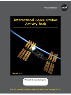
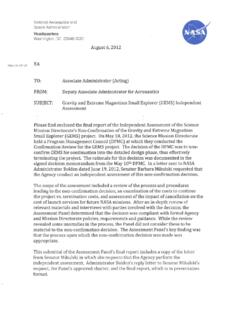
6 6 Safety and Health Safety is an integral part of the culture at the National Aeronautics and Space Administration (NASA). Management, leadership, and employee involvement from all organizations are critical to the success of NASA s safety program. In order to ensure personal safety and a safe test environment throughout the process, the requester shall furnish the facility with the information necessary to perform a hazard assessment of the test article. Additionally, while visiting JSC, the requester shall follow all facility-specific safety and health requirements. A facility safety briefing shall be provided to all personnel prior to the start of the test. The safety briefing will include a review of the laboratory safety rules, potential hazards, and emergency procedures. Test Process Flow The flowchart presented below outlines the basic roadmap and significant milestones between the initial test request and delivery of test data.
7 The flow is separated between Test Requester actions and Facility actions, highlighting interactions and inputs between the Test Requester and the facility Test Director. 7 The test schedule is highly dependent on the complexity of the test, facility availability, and sequence of runs. For time-critical testing, it may be possible to accelerate the schedule, given constraints associated with previous customer commitments. A detailed schedule shall be developed as part of the test planning process following a review of the test objectives and requirements. Typical major milestones are presented below: Note: The schedule is subject to the complexity of test requirements. Proprietary Information The EMI/EMC Test Facility provides for protection of proprietary information and hardware throughout the test process. The Test Requester shall clearly mark all export controlled or proprietary hardware items and data provided with a notice of restriction on disclosure or usage.
8 The Test Director shall safeguard export controlled or proprietary items from unauthorized use and disclosure and ensure that test articles remain secure within the facility and are properly sequestered. Hardware items shall be returned to the Test Requester or disposed of in accordance with the Test Requester s instructions at the completion of the test activity. 8 Test Initiation Phase The test initiation phase establishes the relationship between the Test Requester and the Test Director. The Test Requester shall provide a test request to the Test Director. The test request will be used to determine test feasibility and to develop an estimated cost and a preliminary test schedule. An initial requirements review meeting may be necessary in order to discuss the characteristics of the test article, the test approach, or any special considerations for the test.
9 An onsite tour of the facility is highly recommended for familiarization and to provide an opportunity for an exchange of technical information. Inputs: Test Requester provides test request, identifies Test Article Expert Activities: Facility Test Director reviews test request to determine test feasibility Outputs: Facility delivers preliminary test plan, estimated cost and schedule to Test Requester Test Request The test request outlines the EUT requirements, test objectives, test article description, and preferred schedule. A Test Request Worksheet is provided in Appendix B. This worksheet addresses the basic requirements for testing in the EMI/EMC Test Facility. It is suggested that the Test Requester complete this worksheet to facilitate the development of a preliminary test plan. At a minimum, the test request should include the following information: Test Requirements and Objectives A brief description of the test requirements including, but not limited to, the following: Applicable EMI/EMC requirements/limits/specification ( , customer specification, MIL-STD-461, DO-160) Desired test environment and modes of operation Proposed test approach Test data requirements 9 Test Article Description A brief description of the test article including, but not limited to, the following.
10 Size/dimensions (provide drawings, sketches, photos) Weight Test article interface (electrical, mechanical, fluids, gases, pressure, temperature, other) Special considerations [hazards, cleanliness, compatibility , Material Safety Data Sheets (MSDS)] Handling, storage, and security requirements Schedule Identify the desired start date and the required date for delivery of the data/test report. Schedule and Cost Estimate A preliminary cost and schedule estimate, including major milestones, will be delivered following review of the Test Request Worksheet. Additional details and refinement of the cost and schedule estimate will be worked out with the Test Requester as test planning proceeds, with a final version to be agreed upon prior to the Test Readiness Review (TRR). Test Preparation Phase The detailed test plan and test schedule are finalized during the test preparation phase.