Transcription of ELECTRON DIFFRACTION
1 ELECTRON DIFFRACTIONELECTRON DIFFRACTIONREFERENCEI nstruction Manual: ELECTRON DIFFRACTION Tube - Welch Scientific Co. Cat. No. 2639 - (available atthe Resource Centre).INTRODUCTIONThis experiment is a demonstration of thewave nature of the ELECTRON , and providesa confirmation of the de Broglierelationship:(1) hpwhere = ELECTRON wavelength, h =Planck's constant, p = ELECTRON also provides an introduction to the useof DIFFRACTION in the analysis of guide sheet outlines a method for the analysis of cubic crystal forms, this being useful to youfor interpreting the transmission DIFFRACTION pattern produced by scattering electrons off a thin filmtarget of polycrystalline aluminium.
2 The apparatus also contains samples with hexagonal are pyrolytic graphite targets, and are available both as single crystals and in the methodology of analysis of the hexagonal crystal, and for additional material on cubiccrystals, see the DE BROGLIE WAVELENGTHThe voltmeter measures the accelerating potential of the electrons in the tube. Thus:(2)12mv2f eVorp mvf 2meVwhere vf is the final velocity of the electrons after being accelerated through a potential V. Theabove assumes the non-relativistic approximation. To what degree is this justified? ELECTRON DIFFRACTIONELECTRON DIFFRACTIONS ubstituting in the de Broglie relationship, equation(1);(3) hp h2meV h2/2meVWhen the values of h, m, and e are substituted:(4) (nm) (Volts)BRAGG'S LAWThe case of waves (electromagnetic waves such as x-rays or "matter" waves such as electrons)scattering off a crystal lattice is similar to light being scattered by a DIFFRACTION grating.
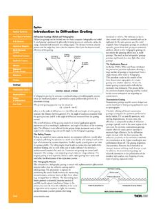
3 However,the three-dimensional case of the crystal is geometrically more complex than the two- (or one-)dimensional DIFFRACTION grating case. Bragg's Law governs the position of the diffracted maxima inthe case of the crystal. A wave diffracted by a crystal behaves as if it were reflected off the planesof the crystal. Moreover there is an outgoing diffracted wave only if the path length differencebetween rays "reflected" off adjacent planes are an integral number of wavelengths. Thusconsidering a beam scattering off two parallel planes of atoms as shown in beam incident on a pair of planes separated by a distance d.
4 (For reinforcement of the scattering from atomsin one plane the usual condition for reflection applies, - angle of reflection equal angle of incidence, asindicated.)The extra path length of the lower ray may be shown to be 2d sin so that maxima in the diffractionpattern will occur when:2d sin = n ,n = 0,1,2,..(5) ELECTRON DIFFRACTIONThis is Bragg's Law. Furthermore, the beam is deflected a total angle 2 . Thus, for our electrondiffraction tube, with maxima registered as spots or rings on the face of the tube, the distance of thespot from the incoming beam axis = R, soR = D tan(deflection) = D tan 2 D 2 (6) where D = distance from target to screen.
5 Combining equations (5) and (6), and taking sin w , then:(7)R n Dd(Note that for the polycrystalline samples mentioned below, r is the radius of the ring.)Note then, that the obtaining of a DIFFRACTION maximum requires that two conditions be met. Not onlymust the angle of deflection bear an appropriate relationship to d and , but also the crystalorientation must be correct to provide an apparent "reflection" off the crystal planes. The way thecrystals are oriented relative to the incoming beam will thus determine the appearance of thediffraction pattern, ELECTRON DIFFRACTION PATTERNSIn relation to DIFFRACTION patterns it is interesting to consider three types of solid matter: singlecrystals, polycrystals and amorphous CRYSTALSS ingle crystals consist of atoms arranged in an orderly lattice.
6 Some types ofcrystal lattices are simple cubic, face centre cubic ( ), and body centrecubic ( ). In general, single crystals with different crystal structures willcleave into their own characteristic geometry. You may have seen singlecrystals of quartz, calcite, or carbon (diamond).Single crystals are the most ordered of the three structures. An ELECTRON beampassing through a single crystal will produce a pattern of spots. From thediffraction spots one can determine the type of crystal structure ( , )and the "lattice parameter" ( , the distance between adjacent (100) planes).Also, the orientation of the single crystal can be determined: if the singlecrystal is turned or flipped, the spot DIFFRACTION pattern will rotate around thecentre beam spot in a predictable DIFFRACTIONM iller indices of some lattice planesPOLYCRYSTALLINE MATERIALSP olycrystalline materials are made up of many tiny single crystals.
7 Most common metal materials(copper pipes, nickel coins, stainless steel forks) are polycrystalline. Also, a ground-up powdersample appears polycrystalline. Any small single crystal "grain" will not in general have the sameorientation as its neighbours. The single crystal grains in a polycrystal will have a randomdistribution of all the possible polycrystal, therefore, is not as ordered as a single crystal. An electronbeam passing through a polycrystal will produce a DIFFRACTION patternequivalent to that produced by a beam passing through series of singlecrystals of various orientations. The DIFFRACTION pattern will thereforelook like a superposition of single crystal spot patterns: a series ofconcentric rings resulting from many spots very close together at variousrotations around the centre beam spot.
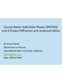
8 From the DIFFRACTION rings one canalso determine the type of crystal structure and the "lattice parameter".One cannot determine the orientation of a polycrystal, since there is nosingle orientation and flipping or turning the polycrystal will yield thesame ring MATERIALSA morphous materials do not consist of atoms arranged in ordered lattices, but in hodgepodge randomsites. Amorphous materials are completely disordered. The ELECTRON DIFFRACTION pattern will consistof fuzzy rings of light on the fluorescent screen. The diameters of these rings of light are related toaverage nearest neighbour distances in MILLER INDICES FOR CUBICCRYSTALSThe Miller indices characterize variousplanes through a crystal lattice.
9 First choosecrystallographic axes, 3a,3b and3cwith the origin at one atom. The Millerindices are defined to be the reciprocals ofthe fractional intercept of the plane with thethree axes, as shown in the figure. If theplane is parallel to a given axis, the index is= 0, corresponding to an intercept of DIFFRACTIONFor a cubic crystal, the distance of the specified plane from the parallel plane which passes throughthe origin is:(8)d aH2 K2 L2where H, K, L are the Miller indices and a = length of a side of the cube. The proof of this is asimple matter of solid lower the Miller indices, the greater the separation between adjacent parallel planes.
10 In addition,the lower indexed planes have a greater density of lattice aluminium target is a powder of small crystal flakes, , it is polycrystalline. Thus thediffraction pattern appears as rings. There are also many possible planes that may be drawn throughthe crystal lattice, and in a powder sample in general all of these will be present. A simple exampleof this is shown in Figure more useful form (as shown below) may be found by multiplying numerator and denominator bythe order of interference, n:(9)d nah2 k2 52where h = nH, k = nK and 5 = nL; n,k, and 5 are also OF RING RATIOSA convenient way of obtaining information from a polycrystalline material's ring pattern is throughthe "method of ring ratios".