Transcription of Electronic Brake Control For 2, 4, 6 and 8 READ …
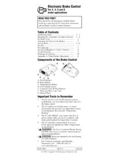
1 P/N 5881 REV C 02/12 Electronic Brake ControlFor 2, 4, 6 and 8 Brake applicationsREAD THIS FIRST:Read and follow all instructions carefully before installing or operating the P3. Keep these instructions with the Brake Control for future reference. Table of ContentsInstallation Guide .. 2 - 3 Mounting P3, Automatic Leveling of Sensor .. 3 - 4 Set Brake Type .. 4 Adjusting the Power to the Brakes .. 5 Setting Boost .. 5 - 6 Reverse .. 7 Set Language .. 7 Set Screen Brightness / Color / Contrast .. 8 Troubleshooting .. 9 Warnings & Cautions .. 10 Appendix A: Trailer Brake Adjustment .. 11 Components of the Brake ControlA. Power ButtonsB. Boost ButtonC. Menu/Options ButtonD. LCD Display ScreenE. Connector (For Wiring Harness)F. Mounting Hole (1 per side)G. Manual KnobImportant Facts to Remember1. Do not mount or activate RF generating items (cell phones, two way radios) near (less than 12") the Brake The P3 employs an inertial sensor.
2 It senses deceleration and generates an output that is based on deceleration, thus the term Proportional Braking .3. The P3 will HOLD your trailer with 25% of power setting while you are at a standstill with Brake pedal applied for longer than 5 seconds. 4. The P3 will Brake proportionally in reverse. It will apply the appropriate Brake voltage based on deceleration. 5. WARNING The Gross Combined Weight Rating (GCWR) must never exceed the vehicle manufac-turers CAUTION Boost not intended to be used during icy road For Technical Assistance and Warranty Information call: 1-888-785-5832 or 2012 Cequent Performance Products, GuideThe P3 can be mounted from 0 degrees to 360 degrees vertically in the direction of travel. (See Diagram for Mounting the P3). Wiring Brake ControlYour P3 Brake Control has a unique connector located at the back of the Control . This connector allows you two options to wire your Brake 1:Use Pigtail Wiring Harness included.
3 This harness can be installed by following the Generic Wiring Guide. Option 2:Use an OEM specific wiring harness. If your vehicle came with a factory tow package that included a 7-way connector, you can purchase a Tekonsha OEM wiring harness with the P3 connector on one end and your specific vehicle s connector on the other. Display Readings after Wiring the P3 After successfully wiring your P3 you should see the following on the LCD display: Power to P3 without trailer connected. Power to P3 with trailer connected Boost feature engaged (B1). Manual Knob Activated without trailer connected. Manual knob activated (with trailer), denotes a hypothetical power output. This value is set using the Power Buttons. Range is to 15 volts. This is an indication of voltage output to electric SCrEEnS3 Power to P3 but display is in power saving mode (no motion or activity for at least fifteen minutes).
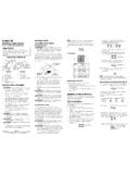
4 Mounting the P3 Traditional Bracket MountA. Mounting BracketB. #8 X 3/8" Machine Screw with Internal Tooth Washer1. CAUTION Drilling or use of longer screws may damage Securely mount bracket to a solid Insert supplied #8 x 3/8" machine screws on each side into the mounting Adjust Control to desired position and tighten screws until Dash Pocket MountA. T Slot MountB. Small Metal BracketC. #8 X 3/8" Self Tapping Screws 1. Securely mount Small Metal Bracket to a solid surface using supplied #8 X 3/8" Self Tapping Securely mount T Slot Mount to Small Metal Bracket using supplied #8 X 3/8" Self Tapping Plug in Insert P3 Brake 0 4 NOTE: 1. Front of the P3 must be horizontal, see below. 2. The P3 must be parallel to direction of travel, see below. Automatic Leveling of the SensorThe P3 will automatically acquire the proper level setting. It will also automatically adjust as you travel up or down hills.
5 Set Brake TypePress Menu/Options Button to view Setup screen. Select/highlight Brake type and Press OK (Menu Button).Select/highlight Electric or Hydraulic and Press OK (Menu Button).Select/highlight Confirm and Press OK (Menu Button).Screen should show Brake Type Setting E (Electric) or H (Hydraulic) in the lower left of of TravelDirection of Travel5 Adjusting the Power to the Trailer Brakes (Prior to setting Boost)Once the Control has been securely mounted, it is necessary to set the power needed to stop the trailer during a braking Connect trailer to tow With engine running set power (with Power Buttons) to indicate Drive tow vehicle and trailer on a dry level paved surface at 25 mph and fully apply Manual Knob. 3 If trailer brakes lock up:q Turn power down using Power If braking was not sufficient:q Turn power up using Power Repeat Step (3) until power has been set to a point just below wheel lock up or at a sufficient force as to achieve maximum braking Using the Brake pedal, make a few low speed stops to check the power setting.
6 Trailer braking is initiated and terminated via the stoplight switch. When the Brake pedal is released, trailer braking will SettingThe boost button was designed to allow a more aggressive setting for your trailer brakes and is available in three levels - B1, B2, B3. Each incremental boost setting increases the sensitivity of the P3 s inertial sensor, enhancing the participation of the trailer brakes during a braking B1 icons on the screen indicate Boost example: With the boost off, during a braking event, the power to the brakes starts out at zero and increases with deceleration. With the boost on level 1, B1, during a braking event, the power automatically starts out at approximately 13% of the power setting and increases with deceleration. With the boost on level 2,B2, or with the boost on level 3, B3, during a braking event, the power automatically starts out at approximately 25% of the power setting and increases with cases where you might want to use the boost button: You like the trailer braking to LEAD the tow vehicle s braking Towing a full vs.
7 Empty trailer Degraded Brake performance (most electric brakes require manual adjustment - see Appendix A or a dealer for adjustment or repair)(Boost Setting continued on next page)Boost On6 See the chart below for recommended Boost settings (indicated with X) for typical Trailer to Vehicle weight your boost setting based on your towing situation, driving preference and condition of your trailer Boost Settings For Optimal Performance Trailer WeighT compared to Vehicle WeighT(with properly adjusted trailer brakes*) WARNING Do not exceed Gross Combined Weight Rating (GCWR) * increased Boost setting may be needed if trailer brakes are worn, see Appendix A or a dealer for Brake adjustment or repair. INCREASING BOOST LEVEL BOOST OFF NOTE: Boost not intended to be used to take place of trailer Brake adjustment or weighs less than VehicleTrailer weighs approXimately same as VehicleTrailer weighs up to 25% more than VehicleTrailer weighs up to 40% more than VehicleTrailer weighs oVer 40% more than Vehicle X X X X X X X X X X X B1 B2 B3 NOTE: 1.
8 Always warm the trailer s brakes before setting the power. Warm trailer brakes tend to be more responsive than cold brakes. To warm trailer brakes, drive a short distance (1/4 mile) at 45 MPH with manual lever engaged enough to cause trailer braking at a low WARNING The power should never be set high enough to cause trailer brakes to lock up. Skidding trailer wheels can cause loss of directional stability of trailer and tow vehicle. 3. The power/Boost may need to be adjusted for different load weights and road Not all trailer brakes will lock up due to various conditions. However, inability to lock up the brakes generally indicates the need for an inspection to determine the When the power is set correctly you should feel unified braking between the trailer and tow vehicle.(BOOST OFF )7 ReverseWhen backing a trailer you can cancel BOOST and HOLD for a period of three minutes. This can be accomplished by pressing the boost button continu-ously for five seconds with the Brake pedal depressed.
9 The display will indicate:Release boost button and the R Arrow icon will three minutes the BOOST and HOLD features will automatically return to your previous :Returning to your previous settings prior to three min-utes can be accomplished by pressing the boost LanguagePress Menu/Options Button to view Setup screen. Select/highlight Help and Press OK (Menu Button).Select/highlight language and Press OK (Menu Button).Select/highlight English (or French or Spanish) and Press OK (Menu Button).8 Set Screen Brightness / Color / ContrastPress Menu/Options Button to view Setup screen. Select/highlight Help and Press OK (Menu Button).Select/highlight Display and Press OK (Menu Button).Select/highlight option to change - Brightness / Color / Contrast and Press OK (Menu Button). Brightness has High / normal / low as options. Select your desired Brightness and Press OK (Menu Button).Color has Pink / White / Blue / light Blue / Cyan / Green / light Green / Orange / Magenta as options.
10 Select your desired Color and Press OK (Menu Button).Contrast has normal / High as options. Select your desired Contrast and Press OK (Menu Button). High contrast makes the text black on colored Storable SettingsPress and hold the boost button for 2 seconds until the Select menu comes down to select the preferred Trailer setting and press OK. This Trailer setting is now ready to be cus-tomized by following the desired setting ( Brake Type, Power Setting, Boost Setting, Language, Brightness/Color/Contrast). To store presets 2-5, repeat above Menu/Options Button to view Setup screen. Select/highlight Help and Press OK (Menu Button).Select/highlight trouble Shoot and Press OK (Menu Button).Select/highlight trouble Shoot and Press OK (Menu Button). The following 4 functions are available for diagnostic and the vehicle battery voltage (black wire).Displays voltage supplied from stoplight switch with Brake pedal depressed (red wire).