Transcription of Electronic Valve with External PCB Guide - Evans Tempcon
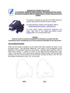
1 Evans Electronic TEMPERATURE CONTROL TROUBLESHOOTING Guide for systems equipped with electric coolant Valve and External PC board. This Troubleshooting Guide covers the electric coolant Valve and control system only. For other HVAC system components, diagnosis, and repair, refer to the separate Evans Tempcon publica-tion titled "Dash Heater-Air Conditioner Troubleshooting Guide , Book Two, Rotary Control Panel Systems". NOTE IF TESTING INDICATES A REPLACEMENT Valve IS NEEDED, IT WILL NEED TO BE REPLACED with OUR KIT RV218809, WHICH INCLUDES A NEW STYLE Valve , WIRING HARNESS, AND INSTRUCTIONS FOR INSTALLATION. THE STYLE OF Valve COVERED BY THESE INSTRUCTIONS IS NO LONGER AVAILABLE.
2 IF TESTING INDICATES THAT A REPLACEMENT CIRCUIT BOARD IS NEEDED, IT WILL BE AVAILABLE FOR A LIMITED TIME AS OUR SERVICE PACKAGE RV218547. WHEN CURRENT INVENTORY IS GONE, IT TOO WILL NEED TO BE REPLACED BY A KIT RV218809. REPLACEMENT POTENTIOMETERS WILL CONTINUE TO BE AVAILABLE AS OUR SERVICE PACKAGE RV218549 FOR AN INDEFINITE PERIOD. There are three common symptoms of an improperly operating electric coolant control system: No heat in the heat mode (Steps - ) Unable to control the temperature in any operating mode (Steps - ) Poor cooling, no cooling, or even heat while operating in A/C mode (Steps - ) Before attempting to troubleshoot, verify that the HVAC system (other than temperature control) is operating correctly.
3 with the vehicle running, test-operate the system and check the following: Blower Motor and 4 operating speeds Mode selector switch and air distribution system A/C system (engine-driven compressor, refrigeration system, etc.). with the vehicle running and the A/C system engaged (Blower turned on, Mode se-lector set to "MAX A/C", Temperature dial rotated to full cool), clamp off the heater inlet hose to see if the A/C system is cooling properly. Test the A/C per-formance using the Evans A/C SYSTEM OPERATIONAL CHECK AND PERFORMANCE GUIDELINES. Once this has been determined (and corrected if necessary), remove the clamp from the coolant inlet hose.
4 If a significant loss in cooling capacity in the A/C system occurs when the clamp is removed, shut the vehicle off, and carefully follow the step-by-step directions listed below for troubleshooting the coolant control system. If a problem is found, repair/correct the fault before proceeding to the next step. When troubleshooting electric and/or Electronic components, care must be taken to prevent component damage while inspecting, using a test meter, light, etc. If questions or concerns arise during the troubleshooting process, contact Evans Tempcon for telephone as-sistance before proceeding further (1-800-878-7174).
5 Remove and inspect the temperature control circuit board, located behind the dashboard. This circuit board is located inside a black plastic housing, which is part of the HVAC wire harness, immediately behind the dash-mounted HVAC control panel. The back of the circuit board (smooth side) should be marked with a black letter "B" or "C" stamped in the upper left corner. If a "B" or "C" is not found, replace the circuit board with a new marked board. "B" and "C" boards are physically and electronically identical. The "C" simply designates a supplier labeling change. Look for any visual signs of Electronic component damage, such as a burned circuit trace or the odor of burnt electronics.
6 If any damage is detected, replace the board. Do Not attempt to solder and/or repair a board. The failure will simply re-occur. Check all of the electrical connections in the black plastic housing. Make sure all of the terminals are properly locked in position, in the housing bottom. Check the terminal/wire crimps in this area for secure crimps and positive electrical contact. If damaged terminals or wires are found, replace the wire harness. Refer to at-tached wiring diagram to verify correct wire color and location in the housing. with the engine running, and the HVAC system operating, use a DC voltmeter to verify 12 volt power to the board housing terminals.
7 Terminal "A" is negative (-), and Terminal D is positive (+). with the board removed, 11-15 volts should be measured across these terminals. If no voltage can be measured across the "A" and "D" terminals, check for a blown fuse, bad ground connection (see Item ), or bad power wire connection. The temperature dial on the control panel is a potentiometer control. Unplug the 3-wire connector from the back of this control. Make sure the socket terminals are fully engaged and locked into the wire connector. Verify correct wire colors and locations in the connector. Check the 3 pin termi-nals on the potentiometer for damage.
8 Rotate the potentiometer knob to verify smooth operation. The knob should rotate freely from the cool stop (blue), to the warm stop (red). Do not force the knob to rotate past the cool or warm stops. Doing so will cause irreparable damage to the potentiometer control. If the knob can be rotated past the internal stop at the full cool and full heat positions, the potentiometer must be replaced. Locate the electric coolant Valve assembly in the heater base unit compartment, near the Evans Heater-Evaporator unit (on the firewall). The electrical connector is located on the outlet side of the Valve . Verify positive electrical connections at the coolant Valve .
9 Unplug the wire har-ness connector from the coolant Valve . The orange connector cap (containing 6 pin holes) can then be removed from the gray connector body. Loose wires/terminals cannot be locked into place in the connector if the orange connector cap is in-stalled. Use a small screwdriver to pry the orange cap off. with the cap removed, verify that each of the 5 socket terminals is pushed into the gray connector until the retaining ring on the terminal is past the locking tab inside the connector housing. The center tab on the orange cap acts as a secondary lock that holds the socket ter-minals in place within the gray connector body.
10 Check the socket terminals for damage. Refer to the attached wiring diagram to verify correct wire color and pin location in the gray connector. Re-install the orange locking cap. Inspect the pin terminals on the coolant Valve for damage. If any pins (5) in the Valve are loose, broken, or missing, replace the Valve . Verify that the port on the outlet side of the Valve is connected to the inlet tube on the heater coil. The coolant supply hose from the engine connects to the inlet side of the Valve . Using the attached coolant Valve installation diagram, verify that the coolant Valve is properly installed in the heater supply hose with the Valve ports in a horizontal position as shown in figure 2 of the installation diagram.