Transcription of ELECTRONICALLY CONTROLLED STEAM …
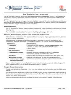
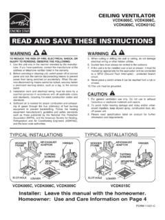
1 1 READ AND SAVE THESE INSTRUCTIONSELECTRONICALLY CONTROLLED STEAM HUMIDIFIERDESIGN SERIES G installation , OPERATIONAND maintenance MANUALE xternal Disconnector Circuit Breaker(Not Provided by Carnes)Water Shutoff Valve(Not Provided by Carnes)Digital OutputRate Meterfor Cylinder 1 Service LightOn-Off-DrainSwitchDigitalDiagnostic PanelBrass CylinderFittingsDrain SolenoidValveCylinderRetainingBandSteamC ylinder #2 SteamCylinder #1 TerminalConnectorsSteam Hose On LightDoorInterlockFillSolenoid ValvePhoto A(Model HCHG Shown)FORM 16789-IISSUED: 04-12 Display forCylinder #2 CARNES COMPANY 448 S. Main St., P. O. Box 930040, Verona, WI 53593-0040 Phone: (608)845-6411 Fax: (608)845-6504 WaterSensorCondensateReturn LineConnection (2)2 INSTALLATIONUNPACKING AND INSPECTION1. Cabinet keys are attached, by ty-rap, to side of Open the cabinet and check for concealed shippingdamage.
2 Report any damage immediately to thecarrier who delivered the The following components are packed in a shippingcarton for connection when installing Distribution STEAM Condensate return Optional accessories may be packed with the cabinetor in the same shipping carton. Large accessoriesmay ship in separate Inside the cabinet is an envelope containing thefollowing items:A. STEAM hose Condensate return line Air gap drain installation operation and maintenance manual , operation addendum, parts replacement catalog, customer satisfaction card, and parts order list THE HUMIDIFIERL ocate the humidifier cabinet level and plumb on a surfaceas close to the STEAM distributor as possible at a convenientheight for servicing. Allow 1 or more on the side for venti-lation and 16 from the bottom of the unit to floor to allow fordrain connections.
3 If there is no common drain within closeproximity of humidifier, a drain pump (Carnes HXWA) maybe required to accommodate this distance. Allow 18 -38 infront of cabinet for door opening or when necessary,remove door with quick release pin. The humidifier mustnever be located outside or where it may be exposed tofreezing temperatures unless a heated, ventilated weatherproof enclosure by others is provided. Do not mount humid-ifiers on a hot or vibrating 1 - MAXIMUM OPERATING WEIGHTWATER SUPPLY CONNECTIONUse ordinary tap water (20 to 120 psi) - DO NOT use hotwater, DI (deionized water), RO (reverse osmosis)water. If softened water is considered, please contactfactory for further 3/8 FPT fitting is provid-ed at the bottom of the humidifier for connection to tap watersupply.
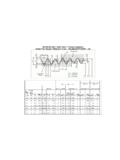
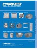
4 A shutoff valve, not provided by Carnes, must beinstalled just ahead of this LINE CONNECTION1. Locate the air gap fitting in accessory bag in unit. Have proper tooling available to attach Connect the air gap drain fitting to the cabinet drainconnection. It may be necessary to cut off some ofthe air gap fitting depending on available Connect the drain or air gap fitting to S or P trap. Useplumbing material capable of handling hot : If the drain water pump accessory package isused, follow instructions included with the drain waterpump , HCAG80 HBDG, HCDG85 HBGG, HCGG105 HBHG, HCHG185 Drain LineConnectionPhoto BMODELFASTENERS REQUIREDHBAG, HCAG4 HBDG, HCDG4 HBGG, HCGG4 HBHG, HCHG6 Table 2 - FASTENER RECOMMENDATION**1/4 Lag Screw, 1 Minimum LengthFasten the mounting bracket to wood studs or solid woodusing fasteners shown in Table 2 below.
5 Place the mount-ing flange on the humidifier cabinet over the mountingbracket. A sheet metal screw should be installed throughthe back of the humidifier cabinet to secure the humidifierto the mounting bracket. Fasteners are not provided Air Gap Fitting(Included)3 STEAM DISTRIBUTOR PIPE LOCATIONEach STEAM cylinder requires a separate distributor pipe, STEAM hose and condensate return line. A cylinder maysupply more than one distributor pipe by using an accessory T fitting but the output cannot be controlledseparately. In a typical installation the humidifier is locatedbelow the duct as shown in Figure A. The length betweenthe humidifier cabinet and the STEAM distributor pipe shouldbe the minimum distance possible. Refer to Table 3 formaximum length that may be installed, based on duct stat-ic pressure.
6 Under less then perfect conditions, (installationissues, routing problems for STEAM and condensate returnhose and extreme STEAM hose lengths) it is possible to losea certain amount of lbs. per hour capacity. See Table AThe maximum length of STEAM hose that may be installedas shown in Figure Ais 12 feet. For a STEAM hose lengthover 12 feet refer to Figure B. A drain T , must be used toremove condensation that occurs in STEAM hose lengthsover 12 feet. It is preferable to have the STEAM hose risevertically from the cabinet and then slope downward to thedistributor pipe as shown. If sufficient headroom is notavailable it is possible to install with an upward slope butthe rise should be 2 in 12 to allow for proper condensatedrainage and STEAM flow.
7 Carnes electrode STEAM humidi-fiers are non-pressurized, maximum of 1/2 psi. It is criticalto provide proper routing of flexible hose and hard tubing tomaximize efficiency and effectiveness. See Figure BMAXIMUM STEAM HOSE LENGTH(Table 3)Duct StaticPressure wg 012 345 Maximum SteamHose Length (Ft.)403530251510 AFFECT ON CAPACITY DETERMINED BY STEAM HOSELENGTH(Table 3-A)DistanceLoss10 CCommon DrainTrapCondensateExtended LengthOptional ifsufficienthead roomis notavailableWhen hose is difficult to supportwithin this length, straight copper tube should be used and insulation linemust pitchdown towarddrain tee NOpockets, sags or horizontal mustbe hoses must pitch down contin-uously to humidifier NOpockets, sags orhorizontal TeeTo DrainMODELSHOSE LOCATION FOR RUNS FROM 12 FEET TO 40 FEETTYPICAL HOSE LOCATIONFOR LENGTHS UP TO12 FEETF igure A-1 Mounting plate must be hoses must pitch down contin-uously to humidifier NOpockets, sags orhorizontal hose is difficult tosupport within thislength, straight copper tube shouldbe used and insulation DISTRIBUTOR PIPE LOCATION(Continued)
8 STEAM distributor pipes must be located on a plumb surface socondensate that forms will run back into the return line. The pipeshould be located in the center of the duct to insure distribution ofsteam into the airstream. A minimum clearance of 4 must bemaintained between the top of the duct and the distributor STEAM distributor pipes are usually located in the supply ductdownstream of the fan. When installed in packaged units the dis-tributor should be mounted just downstream of the fan is important to locate the distributor as far upstream as possiblefrom any obstructions in the ductwork so that air can absorb moisture before it impinges on a surface and accumulates. Theremust be minimum of six feet between the distributor and any fans,coils, filters, dampers, elbows or outlets downstream to reduce thepossibility of GIt is very important that both the STEAM hose and condensatereturn line, whether flexible or hard tubing, be installed so thereare no sags, low points, dips or horizontal runs.
9 The STEAM is at avery low pressure and it cannot overcome any resistance causedby accumulating water standing in the STEAM hose. Accumulationin the condensate return hose will hamper the flow and may causewater to enter the duct work by way of back up in distributor a vertical duct with either upward or downward air flow the distributor pipe should be installed horizontally (Figure E).If multiple pipes are used they should be staggered as shown(Figure F).Figure EFigure FIf it is difficult to install the STEAM hose to prevent sags, it is recommended that copper tube be used as a substitute. If coppertube is used, a minimum of one inch of insulation must be appliedto prevent excessive condensation. A short length of STEAM hosemust be used to connect the cylinder in the humidifier to the copper tube and another short length to connect the copper tubeto the distributor pipe.
10 Size 3/4 copper tube (with 7/8 STEAM hose)can be used with STEAM cylinders having output rates up to 30pounds per hour. Size 1-1/2 copper tube (with 1-5/8 STEAM hose)should be used with STEAM cylinders having output rates over 30pounds per hour. Length restrictions shown in Table 3 also applyto installations where copper tube is used and any use of 90 elbows add approximately three feet of equivalent length, thusnegatively affecting loss of capacity, efficiency and lengths of no longer then 10-20 ft. and proper inclines orrouting, as expressed in this manual , will provide the best chanceof having a proper operating humidifier and efficient and effectivesteam IFigure HPipe InsulationNote:Over time and extendedheat, the situations described in the previous paragraph canoccur.

![Model VEDK — Direct Drive Imperial [IP] Dimensions Roof ...](/cache/preview/a/8/0/7/3/a/f/a/thumb-a8073afad726e9150b75841455430650.jpg)
![SUBMITTAL SHEET MODELS VCDD-C IP [English] Dimensions ...](/cache/preview/e/0/a/3/8/2/6/e/thumb-e0a3826ea292c3adce6bd2e5488fbc67.jpg)

![Model VEBK — Belt Drive Imperial [IP] Dimensions Metric ...](/cache/preview/8/4/0/c/c/c/9/c/thumb-840ccc9c65771a2f0e548a40cb9be23d.jpg)
![Models RSDB, RTDB (Steel) Imperial [IP] Dimensions Metric ...](/cache/preview/e/6/b/1/3/8/1/2/thumb-e6b13812292304bb387911a6f2bfbf54.jpg)