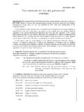
Transcription of ELECTROPLATING VERSUS HOT - DIPPED …
1 This paper was presented at the CARTS-Europe `97 symposium in Prague. ELECTROPLATING VERSUS HOT - DIPPED tinning A COMPARISON OF APPLICATION - EXPERIENCES Gerhard B rstner ( Dipl. Wirtsch. Ing. ) Eckhard Fr hlich (Dipl. Ing.) Feindrahtwerk Adolf Edelhoff GmbH & Co. Am Gro en Teich 33 D-58640 Iserlohn, Germany Phone: +49 2371 43800 Fax *49 2371 40097 E-mail: 1. SUMMARY On the CARTS-EUROPE 96 the topic Lead-Free Electrical Connections has already become a major issue [1]. Due to enviromental reasons and due to technology aspects lead-reduced or lead-free connections will become more important for passive components. This paper presents some recommendations concerning coated lead wires. Two alternative coating methods are described: the ELECTROPLATING process the hot- DIPPED tinning process Specific attention is given to the concentric hot- DIPPED tinning process (FOV).
2 Each method - ELECTROPLATING vs. hot- DIPPED tinning - has it`s specific advantages and characteristics. The paper presents some selected application-experiences in regard to coating characteristics process parameters o mechanical o thermal o chemical solderability properties enviromental aspects Due to the specific advantages of each coating method the manufacturer of passive components has a real choice between both types of coatings. Regarding the lead wire the manufacturer should, depending on the installed process, evaluate his best coating method or adapt his process parameters to the coating properties of the lead wire. 2. INTRODUCTION The soldering process is one of the essential stages within the fabrication process of PCBs. Leaded components has to be tin coated to get a proper electrical and mechanical connection to the board and/or other components.
3 Historicly the hot- DIPPED tinning version has been a very common coating method. Due to it`s specific technology, to wipe off the surplus tin by mechanical tools, the coating showed a more or less eccentric thickness. Within the last 15 years improved electrolytes let the ELECTROPLATING process become an alternative coating method. Especially the concentricity of the ELECTROPLATING has been one of the major arguments, which seemed to prefer the ELECTROPLATING process to the hot- DIPPED tinning process. But nevertheless the hot- DIPPED tinning process has it`s specific characteristics and specific advantages, especially as far as Edelhoff`s concentric version FOV of the hot- DIPPED tinning process is concerned. From the lead wire standpoint the producer of passive components has to put his focus on two topics. Aspects within the manufacturing process are as essential as aspects concerning the finished products.
4 That is why our comming explanations mention both views. 3. COATING METHODS The ELECTROPLATING Process The wire passes pre-treatment baths and cleaning baths, and is then coated in several added steps. Fig. 1 shows the different steps. Fig. 1. The ELECTROPLATING Process The Concentric Hot- DIPPED tinning Process The concentric hot- DIPPED tinning process (FOV) is an improved version of the common known hot- DIPPED tinning process. Edelhoff developed this process about ten years ago according to specific customer requirements. Nowadays there is a significant experience in running this advanced process. Fig. 2 shows the Hot- DIPPED tinning Process Fig 2. The Hot- DIPPED tinning Process The wire passes several cleaning baths and a specific bath with flux. Then the wire gets it`s surface-coating by being solder- DIPPED in tin/lead or pure tin. After cooling and cleaning the coated wire is spooled again.
5 4. THE WHISKER PHENOMENON In discussions the whisker phenomenon is often mentioned as a more theoretical topic. But in reality there were indeed a number of various technical problems, which were caused by whiskers and which created a lot of damage and costs [2]. Therefore for instance Bellcore proposed a restriction on the use of pure tin coatings - as far as electroplated coatings are concerned -, based upon information from an earlier AT&T Bell Laboratories document [3]. Whiskers are fine, capillary single crystals consisting of different materials, which may grow out of the metallic layer and might cause therefore short circuits. Among all metals tin has the strongest tendency to form whiskers. Whiskers have a diameter of 1 to 2 mm and can reach a length of about 3 mm [4]. Fig. 3 shows a SEM micrograph of a whisker from a tin plated terminal on a printed circuit board (1500X) [5].
6 Fig 3. SEM of a Whisker on an Electroplated Terminal Although the exact mechanism of whisker growth isn`t yet understood in detail, tin-whiskers may occur only in electroplated pure tin coatings. As a prevention lead should be included in the tin by at least 2%, or the pure tin plating should be heated above it`s melting temperature [6]. That is why Edelhoff developed the FOV-process, as the coating comes directly from the molten bath and doesn`t form any whiskers. 5. COMPARISON OF SELECTED APPLICATION - EXPERIENCES Concerning coating wires Edelhoff has the option of using the FOV-process as well as the ELECTROPLATING process. Depending on the end-uses, existing specifications, or product philosophies, producers of passive components choose between one or the other coating technology. That is why a comparison of application-experiences should help to get a better idea of finding the strengths of each method.
7 As the ELECTROPLATING process is quite well known with it`s special characteristics, we want to put our focus on essential differences in regard to the concentric hot- DIPPED tinning method (FOV). Characteristics As shown in the hot- DIPPED tin coating is given from a molten bath. Therefore the coating is homogeneous and dense. Unlike that the electroplated coating has a specific column crystal-structur, possibly with caves and holes and special chemicals included. Fig. 4 shows a SEM ( 2000X) of an electroplated tin coating. Fig. 4 SEM of an Electroplated Tin Coating (2000X) Fig. 5 shows the compared hot- DIPPED tin coating (2000X). The coating of the hot- DIPPED tinned wire is in exact accordance with it`s bath parameters. If 40% lead and 60% tin is used, you`ll find exactly this L40 coating on the wire. Unlike that there might be variations of up to 5% in the lead content of an electroplated wire due to special physical phenomenons within the galvanic process.
8 The hot- DIPPED tinning process doesn`t know a separation of tin / lead during the process. Fig. 5 SEM of a FOV Hot- DIPPED Tin Coating (2000X) Electroplated coatings need added ingredients within the electrolytic bath to get a proper coating with it`s specific optical and mechanical characteristics. Especially if bright and shiny surfaces are needed the electroplated coating tends to be brittle in comparison to hot- DIPPED coatings. Another significant difference between both technologies causes from the intermetallic zone between core material and coating. Fig. 6 shows a cross section through such a zone. Fig. 6 Cross Section through an Intermetallic Zone In hot- DIPPED tin coatings the intermetallic - and - phase is set up from the very beginning. As a result from that you get a very good bonding between the core material and the tin coating. Hidden failures in regard to the bonding are unlikely, as there will be no coating on unproper prepared surfaces, and possible QC-tests stress the intermediate bonding just after production of the coated wire, so that possible failures would be visible.
9 Unlike this the intermediate zone of an electroplated wire is growing from zero, depending on time and temperature. That is why a certain time is needed till the intermediate zone of an electroplated coating has a certain thickness. Fig. 7 shows examples of growth of the intermetallic zone by using both coating methods. Fig. 7 Growth of the Intermetallic Zone Depending on the core-wire an intermediate barrier-layer might be necessary, if for instance bronze has to be electroplated with tin. This barrier coating isn`t necessary at all by using the FOV process. There are even special applications known, where hot- DIPPED tinning and ELECTROPLATING technologies are combined. Process Parameters The fabrication process of passive component as well as the soldering process on the PCB lead to special impacts on the surface-coating of the lead wire. Depending on the coating method producers would get different results concerning the processability of the wire as well as concerning the properties of the finished component.
10 The following mechanical, thermal and chemical properties. Mechanical Properties On the CARTS-USA `97 symposium Edelhoff presented already a comparison of surface hardness and abrasion strength for both coating technologies [7]. Fig. 8 and Fig. 9 show the results of this research. Fig. 8 Surface Hardness of Tinned Wires In general hot- DIPPED tinned coatings tend to have higher surface hardness and higher abrasion strength compared to electroplated coatings. In comparison to tin/lead alloys pure tin gives superior results in regard to surface hardness and abrasion strength. Therefore the hot- DIPPED tinning process can be an appropriate coating method, if such surface conditions are dominant factors. Fig. 9 Wear and Tear of Tinned Wires Besides that the tin-layer thickness influences the surface properties as well; both, the coating method as well as the layer thickness have impact on the possible speed of the production process itself.