Transcription of ELG3311: Assignment #4 - Engineering
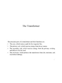
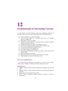
1 1 ELG3311: Assignment #4 Problem 9-13: A , 120-V series dc motor has an armature resistance of and a series field resistance of . At full load, the current input is 58 A, and the rated speed is 1050 r/min. Its magnetization curve is shown in Figure P9-5. The core losses are 200 W, and the mechanical losses are 240 W at full load. Assume that the mechanical losses vary as the cube of the speed of the motor and that the core losses are constant. (a) What is the efficiency of the motor at full load? (b) What are the speed and efficiency of the motor if it is operating at an armature current of 35 A? (c) Plot the torque-speed characteristic for this motor. Figure P9-5 The magnetization curve for the series motor in Problem 9-13.
2 This curve was taken at a constant speed of 1200 r/min. 2 Solution: (a) The output power of this motor at full load is WhpWhpPout5595)/746(*) (== The input power is WIVPLTin6960)58)(120(=== Therefore the efficiency is % = =inoutPP (b) If the armature current is 35 A, then the input power to the motor will be WIVPLTin4200)35)(120(2=== The internal generated voltage at this condition is ) )(35(120)(22=+ =+ = And the internal generated voltage at rated conditions is ) )(58(120)(11=+ =+ = From Figure P9-5, the internal generated voltage EAo,2 for a current of 35A and a speed of no = 1200 r/min is EAo,2 = 115 V, and the internal generated voltage EAo,1 for a current of 58A and a speed of no = 1200 r/min is EAo,1 = 134V. So, the final speed is min/1326)1050( ,1,122rnEEEEnAoAoAA=== The power converted from electrical to mechanical form is WIEPAA conv3759)35)( (22=== The core losses in the motor are 200W, and the mechanical losses in the motor are 240W at a speed of 1050 r/min.
3 The mechanical losses in the motor scale proportionally to the cube of the rotational speed. So the mechanical losses at 1326 r/min are 3 WPnnPmechmech483)240(10501326313122= = = Therefore, the output power is WPPPP coremechconvout30762004833759= = = And the efficiency is % = =inoutPP (c) A MATLAB program to plot the torque-speed characteristic of this motor is shown below: % M-file: % M-file to create a plot of the torque-speed curve of the % the series dc motor in Problem 9-13. % Get the magnetization curve. Note that this curve is % defined for a speed of 1200 r/min. load if_values = p95_mag(:,1); ea_values = p95_mag(:,2); n_0 = 1200; % First, initialize the values needed in this program. v_t = 120; % Terminal voltage (V) r_a = ; % Armature + field resistance (ohms) i_a = 9:1:58; % Armature (line) currents (A) % Calculate the internal generate voltage e_a.
4 E_a = v_t - i_a * r_a; % Calculate the resulting internal generated voltage at % 1200 r/min by interpolating the motor's magnetization % curve. Note that the field current is the same as the % armature current for this motor. e_a0 = interp1(if_values,ea_values,i_a,'spline' ); % Calculate the motor's speed, using the known fact that % the motor runs at 1050 r/min at a current of 58 A. We % know that % % Ea2 K' phi2 n2 Eao2 n2 % ----- = ------------ = ---------- % Ea1 K' phi1 n1 Eao1 n1 % % Ea2 Eao1 % ==> n2 = ----- ------ n1 % Ea1 Eao2 % % where Ea0 is the internal generated voltage at 1200 r/min % for a given field current. 4% % Speed will be calculated by reference to full load speed % and current. n1 = 1050; % 1050 r/min at full load Eao1 = interp1(if_values,ea_values,58,'spline') ; Ea1 = v_t - 58 * r_a; % Get speed Eao2 = interp1(if_values,ea_values,i_a,'spline' ); n = ( ).
5 * (Eao1 ./ Eao2) * n1; % Calculate the induced torque corresponding to each % speed from Equations (8-55) and (8-56). t_ind = e_a .* i_a ./ (n * 2 * pi / 60); % Plot the torque-speed curve figure(1); plot(t_ind,n,'b-','LineWidth', ); hold on; xlabel('\bf\tau_{ind} (N-m)'); ylabel('\bf\itn_{m} \rm\bf(r/min)'); title ('\bfSeries DC Motor Torque-Speed Characteristic'); grid on; hold off; Problem 9-15: A 300-hp 440-V 560-A, 863 r/min shunt dc motor has been tested, and the following data were taken: Blocked-rotor test: VA = V exclusive of brushes VF = 440 V IA = 500 A IF = A No-load operation: VA = V including brushes VF = 440 V IA = A n = 863 r/min What is this motor s efficiency at the rated conditions?
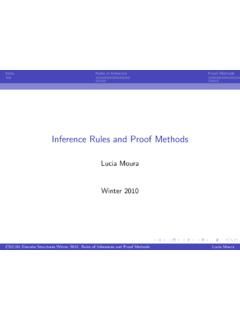
6 [Note: Assume that (1) the brush voltage drop is 2 V, (2) the core loss is to be determined at an armature voltage equal to the armature voltage under full load, and (3) stray load losses are 1 percent of full load.] Solution: The armature resistance of this motor is === ,,brAbrAAIVR Under no-load conditions, the core and mechanical losses taken together (that is, the rotational losses) of this motor are equal to the product of the internal generated voltage EA and the armature current IA, since this is no output power from the motor at no-load conditions. Therefore, the rotational losses at rated speed can be found as 5 ) )( ( ) )( (2442===== = = The input power to the motor at full load is )560)(440(=== The output power from the motor at full load is straybrushrotcuinoutPPPPPP = The copper losses are ) )(440() ()560(22=+=+= The brush losses are WIVPA brushbrush1120)560)(2(=== The stray load losses are ) )( (%1=== Therefore, = = The motor s efficiency at full load is % = =kkPPinout Problem 9-22: The magnetization curve for a separate excited dc generator is shown in Figure P9-7.
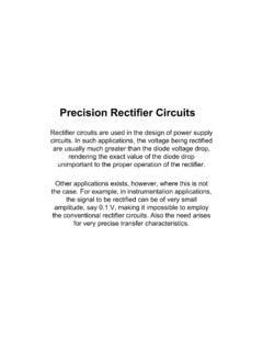
7 The generator is rated at 6 kW, 120 V, 50 A, and 1800 r/min and is shown in Figure P9-8. Its field current is rated at 5 A. The following data are known about the machine: = = ==24120 FFRVV 6 Answer the following questions about this generator, assuming no armature reaction. (a) If this generator is operating at no load, what is the range of voltage adjustments that can be achieved by changing Radj? (b) If the field rheostat is allowed to vary from 0 to 30 and the generator s speed is allowed to vary from 1500 to 2000 r/min, what are the maximum and minimum no-load voltages in the generator? Figure P9-7 The magnetization curve for Problem 9-22. This curve was taken at a speed of 1800r/min. Figure P9-8 The separately excited dc generator in Problem 9-22.
8 7 Solution: (a) If the generator is operating with no load at 1800 r/min, then the terminal voltage will equal the internal generated voltage EA. The maximum possible field current occurs when Radj = 0 . The current is ARRVIadjFFF5024120max,=+=+= From the magnetization curve, the voltage EAo at 1800 r/min is 129 V. Since the actual speed is 1800 r/min, the maximum no-load voltage is 129 V. The minimum possible field current occurs when Radj = 30 . The current is ,=+=+= From the magnetization curve, the voltage EAo at 1800 r/min is V. Since the actual speed is 1800 r/min, the minimum no-load voltage is 87 V. (b) The maximum voltage will occur at the highest current and speed, and the minimum voltage will occur at the lowest current and speed.
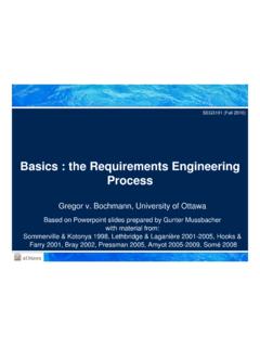
9 The maximum possible field current occurs when Radj = 0 . The current is ARRVIadjFFF5024120max,=+=+= From the magnetization curve, the voltage EAo at 1800 r/min is 129 V. Since the actual speed is 2000 r/min, the maximum no-load voltage is VEnnEAooA143)129(18002000=== The minimum possible field current occurs when Radj = 30 . The current is ,=+=+= From the magnetization curve, the voltage EAo at 1800 r/min is V. Since the actual speed is 1500 r/min, the minimum no-load voltage is ) (18001500=== 8 Problem 9-25: The machine in Problem 9-22 is reconnected as a shunt generator and is shown in Figure P9-9. The shunt field resistor Radj is adjusted to 10 , and the generator s speed is 1800 r/min. (a) What is the no-load terminal voltage of the generator?
10 (b) Assuming no armature reaction, what is the terminal voltage of the generator with an armature current of 20 A? 40 A? (c) Assuming an armature reaction equal to 200 A turns at full load, what is the terminal voltage of the generator with an armature current of 20 A? 40 A? (d) Calculate and plot the terminal characteristics of this generator with and without armature reaction. Figure P9-9 The shunt dc generator in Problem 9-25 and 9-26. Solution: (a) The total field resistance of this generator is 34 , and the no-load terminal voltage can be found from the intersection of the resistance line with the magnetization curve for this generator. The magnetization curve and the field resistance line are plotted below. As you can see, they intersect at a terminal voltage of 112 V.


![The Delta Sequence - - - [n] - Institute of Electrical and ...](/cache/preview/4/5/f/4/3/f/1/e/thumb-45f43f1eaf2ef1960b4bc76c800b38e3.jpg)