Transcription of Embedded Automobile Engine Locking System, Using GSM ...
1 Embedded Automobile Engine Locking System, Using GSM Technology Jayanta Kumar Pany1 & R. N. Das Choudhury2. 1. Dept. of Electronics and Communication Engineering, Raajdhani Engineering College, BPUT, Odisha, India 2. Dept. of Electronics and Instrumentation Engineering. ITER, SOA University, Odisha, India E-mail : Abstract - This paper deals with the design & development of an Embedded system, which is being used to prevent /control the theft of a vehicle. The developed instrument is an Embedded system based on GSM technology. The instrument is installed in the Engine of the vehicle. An interfacing GSM modem is also connected to the microcontroller to send the message to the owner's mobile. The main objective of this instrument is to protect the vehicle from any unauthorized access, through entering a protected password and intimate the status of the same vehicle to the authorize person (owner) Using Global System for Mobile (GSM) communication technology.
2 This system deals with the concept of network security. The main concept in this design is introducing the mobile communications into the Embedded system. The entire designed unit is on a single board. Keywords - Pass Word, GSM Modem, AT Commands, Interfacing, I2C, RS232 and UART protocols. I. INTRODUCTION 3. 4x3 Matrix keypad In these days, Automobile thefts are increasing at an 4. 16x2 Liquid crystal display (LCD). alarming rate all over the world. So to escape from these 5. 12V Relay and DC Fan thieves most of the vehicle owners have started Using the theft control systems. The commercially available 6. GSM Modem anti-theft vehicular systems are very expensive. Here, 7. GSM Mobile we make an attempt to develop an instrument based on 8051 microcontroller and operated Using GSM 8.
3 MAX232 line driver technology. The instrument is a simple and low cost 9. 24C02 E2 PROM. vehicle theft control Embedded system. 10. L293D motor driver & DC motor The Global System for Mobile communications 11. Buzzer (GSM) is the most popular and accepted standard for 12. DB9 connector mobile phones in the world established in 1982 and it operates in 900 MHz frequency. Over billion people use Microcontroller Unit: GSM service across the world. The utility of the GSM. The AT89S52 is a low-power, high-performance standard makes international roaming very common complementary metal-oxide semiconductor (CMOS) 8- between mobile phone operators, enabling subscribers to bit microcontroller with 8K bytes of flash programmable use their phones in many parts of the world.
4 GSM. and erasable read only memory (FPEROM). The device differs significantly from its predecessors in both is manufactured Using Atmel's high-density nonvolatile signaling and speech clarity, as its channels is digitized. memory technology and is compatible with the industry It means that the GSM system is now considered as a standard 80C51 and 80C52 instruction set and pin out. third generation (3G) mobile communication system. The on-chip flash allows the program memory to be reprogrammed in-system or by a conventional II. COMPONENTS, INTERFACINGS AND nonvolatile memory programmer. By combining a PROTOCOLS: versatile 8-bit central processing unit (CPU) with flash 1. AT89S52 Microcontroller on a monolithic chip, the Atmel AT89S52 is a powerful 2.
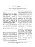
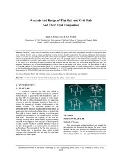
5 DC Power supply unit microcontroller, which provides a highly flexible and International Journal of Instrumentation, Control and Automation (IJICA) ISSN : 2231-1890 Volume-1, Issue-2, 2011. 49 Embedded E Autom mobile Engine L. Locking System, Using GSM Tecchnology cost effectivee solution to many embeedded control applications. Fig. F 02 : Circuitt Diagram of Power P Supply Thiss transformer steps down the incomingg line voltage depending onn the needs off the power suupply. This alteernating voltagge is then fed to the rectifierr. The rectifier is a diodee circuit that converts the ac to pulsatingg dc. This puulsating dc is then t applied to t the filter cirrcuit. The filtter is a circuuit that reducees the variationns of the dc vooltage.
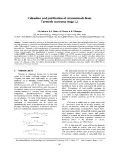
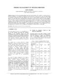
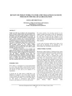
6 Here thhe capacitor iss used as a filter. The filterred dc is thenn fed to a vooltage regulator stage. Thee voltage reggulator is useed to Fig. 01 : Bloock Diagram maintainn a constant vooltage at the poower supply output. It also provides p a furtther smoothingg of the dc vooltage. he microcontroller: Features of th We are Using an IC 78057 as voltage regulator to get a 1. It is a 8-bit microcoontroller with 9 KHz. of 5V outpuut voltage. machhine cycle 4X3. 3 Matrix Keypaad: 2. It hass got a externall crystal oscillaator with Keyypads and LC CDs are the most widely used MHz frequ uency input/ou utput devices. In this sectioon, we first diiscuss 3. 8K byytes of flash ROM and 256 bytes b of RAM keypad fundamentals,, along with key press andd key detectionn mechanismss, and then itt is shown howh a 4.
7 4 bidiirectional I/O ports p with 8 pin ns each keypad is interfaced to an 8051 C. Keypadds are organizeed in a matrix of rows and columns. The CPU. 5. Threee 16-bit timer/ccounters with 4 modes of accessess both rows annd columns through ports. When W a operaation. key is pressed, p the rrow and coluumn are conneected;. 6. A sixx-vector two-levvel interrupt arrchitecture otherwisse there is no connection betw ween them. 7. A full duplex serial port(UART) with w Scannin ng and identifyying the key pressed: p uency frequ 8. 8-bit data bus and 16 bit address bus b DC Powerr Supply Unit: The DC power supplly unit is divvided into 4. elements as beelow. 1. 230V. V/12V step dow wn Transformerr. 2. Bridgge Rectifier witth 4 x 1N4007 diodes.
8 3. 470 F/35V Capacittor as a Filter. 4. 7805 Voltage Regulator IC. Fig. 03 : Scheematic diagram m of Keypad International Journal of Instrumentation, I A) ISSN : 2231-1890 Volume-1. , Control and Auutomation (IJICA 1, Issue-2, 2011. 50. Embedded E Autom mobile Engine L. Locking System, Using GSM Tecchnology In the above figure f a 4X3 matrix m keypadd is connected 12V. V Relay and DC. C Fan: between two ports. p The rows are connected to an output Thee relay is an eleectromagnetic switch. When relay port and the columns c are coonnected to an Input port. Iff is activaated, then it closes the loopp of ignition, hhence no key has been b pressed, reading r the innput port will start the Engine . Whenn relay is de-acctivated, it openns the yield 1s for alll columns sincce they are alll connected to loop off ignition, heence stop thhe ignition of the high voltage (Vcc).
9 ( If all thhe rows are grrounded and a automobbile. A DC F Fan is conneccted with the relay key is pressed d, one of the coolumns will haave 0 since the replicating the automoobile Engine to verify the operration key which is pressed p provid des the path too ground. It is of the syystem. the function of the microconntroller to scann the keyboard continuously tot detect and identify the key k which has GSM. M Modem: been pressed. Thee GSM/GPRS Modem com mes with a serial Liquid Crrystal Display (LCD). ( unit: interfacee through which the modemm can be contrrolled Using AT. A command innterface. Heree a SIMCOM made A 16x2 character c Line LCD modulee is a parallel (SIM300 0) modem intterfaced with the microconttroller port module. An 8051 proggram must inteeract with the operatess in 900 MHz frequency.))
10 Fr outside world d Using inputt and output devices that communicate directly with a human being. One of the Thee protocol usedd by GSM moodems for setuup and most commonn devices attacched to an 80051 C is an control is based on thhe AT-Comm mand set. The GSM. LCD display. LCD requires 3 control linees as well as 8 modem specific comm mands are adappted to the serrvices I/O lines for the t data bus. So this LCD will w require a offered by a GSM modemm such as: a text messaaging, total of 11 dataa lines. calling a given Phoone number, deleting meemory locations etc. Since the main objective forr this applicatiion is to shoow how to sennd and receivee text messagees, only a subsset of the AT-C. Command set needs to be im mplemented. Thhe following section describees the AT-Com mmand set.