Transcription of EMI Issues in Modern - EMC Society - Home
1 66 2009 IEEEB iographiesMariano Giunta received the degree in Elec-tronic Engineering from the Politecnico of Torino-Italy in 1989. In the same year, he joined Telecom Italia/TILAB (Telecom Italia Laboratory, whose main activities are engi-neering, innovation and testing in the field of telecommunication); since that time, he has been involved in studies, standardization and testing activities on EMC telecommunication topics. Currently, he is responsible for the Telecom Italia EMC laboratory. He has lec-tured on EMC measurements at the Politecnico of Torino and he is active in several EMC related national and international standard-ization committees including IEC, ETSI, and Ianoz taught EMC as a Professor of the Electrical Department of the Swiss Federal Institute of Technology of Lau-sanne until 2001.
2 He is now an honorary professor. He was engaged in research activities concerning the calculation of electromagnetic fields, transient phenom-ena, lightning and EMP effects on power and telecommunication networks and power line communica-tion. Professor Ianoz is a past Chairman of the Subcommittee 77B (HF phenomena) of the International Electrotechnical Commission (IEC). He is an EMP Fellow, IEEE Fellow and Doctor Honoris Causa of the Technical University of Saint-Petersburg. EMCEMI Issues in Modern Power Electronic SystemsFiruz Zare, Queensland University of Technology, Brisbane, QLD, Australia, Email: Electromagnetic compatibility of power electronic systems becomes an engineering discipline and it should be considered at the beginning stage of a design. Thus, a power electronics design becomes more complex and challenging and it requires a good communication between EMI and Power electronics experts.
3 Three major Issues in designing a power electronic system are Losses, EMI and Harmonics. These Issues affect system cost, size, efficiency and quality and it is a trade-off between these factors when we design a power IntroductionPower Electronics is Power Processing. It is an application of electronic circuits to control a power converter in order to pro-vide adjustable DC or AC voltage for different loads. Power Electronics can be split into a Power and an Elec-tronic circuit. The power circuit converts an unregulated in-put power from AC or DC type to a regulated AC or DC voltage or current and delivers it to a load. The electronic circuit controls the converter by measuring the input and output voltages and/or currents and generates signals for the power circuit. In a power electronic system, the flow of elec-tric energy is controlled based on a load demand.
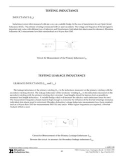
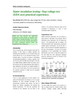
4 In a power electronic system, line and EMI filters are important sections of a system. There are different load and utility requirements which should be fulfilled to reduce noise and harmonic levels of the system. Fig. 1 shows a block diagram of a power elec-tronic system. Main aims in Modern power electronic systems are to deliver the power with maximum efficiency, minimum cost and weight in an integrated circuit. Power electronics has a significant role in different industries when power processing is required such as in computers, telecommunications, motor drives, cars and alternative energy systems. In general, circuit elements in most electrical systems are re-sistors, capacitors, magnetic elements and transistors as shown in Fig. 2. Some of these components may be used in low or high power systems. In most electronic circuits in which efficiency is not a main concern, circuit elements consist of resistors, capacitors and transistors.
5 It is difficult to include magnetic elements into in-tegrated circuits as they are large in size compared to capacitors and resistors. The transistors may operate in linear or switched mode as they transfer low power power converters, efficiency is a main concern. Power cir-cuits consist of capacitors, magnetic elements and transistors in switched mode. Resistors and power switches in linear mode are not used in most power circuits due to significant losses generated by current through these components which decrease the efficiency and cause thermal problems. In power electronics high voltages and high currents are processed by fast switching to reduce losses which are signifi-cant sources of electromagnetic noise and it cause additional costs. Main EMI research targets in power electronics are:Analysis of electromagnetic emissions by measurements, modelling and simulations 67 2009 IEEED evelopment active EMI filters in high power converters to suppress EMI noiseIntegration of power and electronic circuits is the market demand which intensifies the challenges.
6 Advances in semicon-ductor technology brought fast power switches in the market to increase efficiency and power density of systems. This progress has helped power electronics engineers to improve system ef-ficiency and performance but on the other hand it comes along with more need to comply with EMC requirements. As the electromagnetic compatibility of power electronic systems be-comes an engineering discipline it should be considered at the beginning stage of a design. Thus, a power electronics design becomes more complex and challenging and it requires a good communication between EMI and Power electronics experts. 2. Power SwitchesA Modern power electronic system is a power processing system based on Pulse Width Modulation (PWM) technique. In a control system, a desired PWM signal is synthesized and trans-ferred to power switches through gate drives to generate the same waveform at different voltage or current level.
7 Thus, the power switches chop high voltages and/or currents when they are turned on and off. When we consider a power switch as an ideal switch, that means the switch can handle unlimited current and blocks un-limited voltage. The voltage drop across the switch and the leakage current through the switch are considered zero with no rise and fall times as shown in Fig. 3. This assumption helps us to analyze a power circuit at low frequency but for practical con-siderations we should consider real power switches with three main Issues , Losses, Electromagnetic Interferences (EMI) and Harmonics!In real case, ideal switches do not exist. During switching transients, there are significant switching losses associated with dv/dt and di/dt. These phenomena depend on several Issues such characteristics of power switches, control signals, gate drives, stray parameters and operating points of the system.
8 3. LossesThere are different types of losses in a power converter such as: Conduction and switching losses in power switches Losses due to charging and discharging stray components in a power converterLosses in a controller When a switch is turned on or off, energy is lost during the switching transients as the operating point of the switch is changed from on (off) to off (on) state through an active state. This type of energy loss is called switching loss of the power switch and it depends on voltage across the switch, current through the switch and the switching a switch is off, normally a leakage current through the switch is very small and we ignore the energy loss associated with the off-state. But when the switch is on, the energy loss depends on current through the switch and a forward voltage of the switch.
9 This type of energy loss is called conduction loss of the switch. The average power loss in a switch over one switching cycle is given by the following equation which consists of the con-duction and switching losses:Ps51 Tsw 3 Tsw0is vs dt5 Pcond1 PswAssuming that the on and off switching times are small compared to switching cycle, Tsw, and the leakage current is negligible, Ioff50. Thus the conduction loss is given by:Fig. 1. A block diagram of a power electronic ConverterFeedback SignalFilterInput Filter: Lineand EMI Filter Controller Control SignalFilterOutput Filter: LC iin(t)iout(t)vin(t)vout(t)Fig. 2. Circuit elements in electrical andTr ansformersLinear ModeSwitched_ModeCircuitElementsFig. 3. Voltage and current waveforms in an ideal + S68 2009 IEEEP cond 5 Von3 Ion3DD 5 tonTswWhere ton is the time when the switch is in on-state, Von is a voltage drop across the switch, Ion is a current through the switch assuming it is constant in magnitude and D is a duty cycle.
10 The switching loss should be calculated based on instanta-neous current and voltage waveforms. Psw5fswa3t11tsw_ont1is vs dt13t21tsw_offt2is vs dtbWhere, t1 and t2 are the times when gate signals are applied to turn on and off the switch, respectively; tsw_on and tsw_off are turn-on and turn-off switching times. This equation shows that the switching loss is proportional to the switching frequency. Thus increasing the switching frequency increases the switch-ing losses!In all power electronic systems, there are stray inductances and capacitances due to interconnections between the power components via wire, conductor plates or any other types of conductors. In a power electronic circuit when a power switch is turned on and off, stray inductance associated with a current loop is charged and discharged as shown in The energy stored in the inductor depends on the current magnitude and inductance value.