Transcription of EML 2322L – MAE Design and Manufacturing Laboratory ...
1 EML 2322L MAE Design and Manufacturing Laboratory Dimensioning Rules 1. Each dimension should be given clearly so it can be interpreted in only one way. 2. Dimensions should not be duplicated or the same information given in two different ways (dual dimensioning excluded). 3. Dimensions should be given between points or surfaces that have a functional relation to each other or that control the location of mating parts. 4. Dimensions should be given so it will not be necessary for the machinist to calculate, scale, or assume any dimension. 5. The machinist should not be expected to assume a feature is centered (as a hole on a plate), so always provide a location dimension from the appropriate datums. 6. Dimensions should be attached to the view where the shape is best shown and the features dimensioned are shown true shape. 7. Dimensioning to hidden lines should be avoided wherever possible. Use auxiliary cross sectional views instead.
2 8. Dimensions should not be placed on a view unless clarity is promoted and long extension lines are avoided. 9. Longer dimensions should be placed outside all intermediate dimensions so that dimension lines will not cross extension lines. 10. In machine drawing, all unit marks should be omitted, except when necessary for clarity; for example, 1" REAMER or 1mm DRILL. 11. Detail dimensions should "line up" in chain fashion. 12. Dimension lines should be spaced uniformly throughout the drawing. They should be at least 3/8" from the object outline and 1/4 apart. 13. No line of the drawing should be used as a dimension line or coincide with one. 14. Dimension lines should not cross, if avoidable. Dimension lines and extension lines should not cross, if avoidable. Extension lines may cross each other. When extension lines cross extension lines or visible lines, no break in either should be made. 15. A center line may be extended and used as an extension line, in which case it is still drawn like a center line.
3 16. Leaders for notes should be straight, not curved, and point to the center of circular views of holes wherever possible. Leaders should slope at 45 , 30 or 60 with horizontal but may be made at any convenient angle except vertical or horizontal. 17. Leaders should extend from the beginning or from the end of a note, the horizontal "shoulder" extending from mid height of the lettering. 18. Dimension figures should be approximately centered between the arrowheads, except that in a "stack" of dimensions, the figures should be "staggered." 19. Dimension figures should be about 1/8 high for whole numbers and 1/4 high for fractions. 20. Dimension figures should never be crowded or in any way made difficult to read. 21. Dimension figures for angles should generally be lettered horizontally. 22. Notes should always be lettered horizontally on the sheet. 23. Notes should be brief and clear, and the wording should be standard in form. 24.
4 Finish marks should be placed on the edge views of all finished surfaces. 25. Finish marks should be omitted on holes or other features where a note specifies a machining operation. 26. A cylinder is dimensioned by giving both its diameter and length in the rectangular view, except when notes are used for holes. A diagonal diameter in the circular view may be used in cases where clarity is gained thereby. 27. Holes to be bored, drilled, reamed, and so on are size-dimensioned by notes in which the leaders preferably point toward the center of the circular views of the holes. Indications of Manufacturing processes may be omitted from notes. 28. Drill sizes are preferably expressed in decimals. 29. Circles (holes) are dimensioned by the DIAMETER, arcs (fillets) by the RADIUS. 30. A diameter dimension value should always be preceded by the symbol . 31. A radius dimension should always be preceded by the letter R. The radial dimension line should have only one arrowhead, and it should pass through or point through the arc center and touch the arc.
5 32. When there are several rough, non-critical features obviously the same size (fillets, rounds, ribs, etc.), it is necessary to give only typical (abbreviation TYP) dimensions or to use a note. 33. Decimal dimensions should be used for all machining dimensions. Decimal dimensions less than should be preceded with a leading zero ( ). 34. Never show hidden lines in isometric drawing views, but always show tangent lines. 35. Never shade orthographic or isometric drawing views. 36. Always show hidden lines in orthographic views. 37. Suppress fastener threads to unclutter assembly drawings. 38. Whenever possible place dimensions outside objects rather than inside their outlines. 39. Place dimensions pertinent to part geometry in the detail drawing and dimensions pertinent to positioning the part with respect to others in the assembly drawing. Copyright Notice: many of these rules were taken from an excellent document produced by Dr.
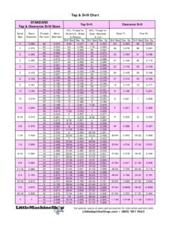
6 Tommy G. Barker and found on his website here. THRU;CSINK X ;4 PLACES ++ THRU #22 THRU;10-24 UNC THRU;4 PLACES 1/4 " .157 THRU;10-24 UNC THRUX Rule 35X Rule XX Rule 34X Rule 2X Rule 2X Rule 4,5,20 Rule 7 XX Rule 10X Rule 9,14 Rule 6 X X Rule 12,13X Rule 18 Rule 36 XRule 28 XX Rule 11,20X Rule 16X Rule 30X Rule 29 Rule 33 XRule 33 XX Rule 16 Shaft Clamp BracketSHEET 1 OF :54321 REVXSIZEAEML2322L-010 DRAWNDESIGNEDJ. DERSCHM. BRADDOCKPLACES IN DIMSWELDINGCUT OFF (SAW, BURN, SHEAR)MACHININGTOLERANCE UNLESS NOTEDOPERATIONSCALE: 1:1 QTY: 1 DIMS IN INCHESMAT'L: ALUMINUMBREAK ALL EDGESFINISH ALL SURFACESS olidWorks Student Edition. For Academic Use Only.