Transcription of ENERGY Manufacturing Company, Inc.
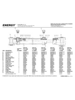
1 Page 1 of 2 Form 44833 XRev. 5/201344833X Rev03/13 IMPORTANT INFORMATION REGARDING VALVE OPERATIONIf the valve kicks out of the retract mode into any position other than neutral, or if the valve spool does not move freely in all phases of operation, USE OF THE VALVE MUST BE DISCONTINUED UNTIL THE VALVE IS REPAIRED AND PROPER FUNCTION IS REGAINED. Please call ENERGY Manufacturing (319-465-3537) for technical FOR REPLACEMENT OF SEALS IN THE LOG SPLITTER KICKOUT VALVE ASSEMBLY **NOTE** these instructions apply to replacing the seals in the ENERGY DSKCVA-200 series log splitter valves. is possible to replace the seals without removing the valve from the hydraulic system. Be certain the valve is clean and dry. If you prefer, dismount and disconnect the valve from the hydraulic system and secure the valve in a vise by gripping on the valve feet.
2 In either case, be certain to place the valve spool in the center, neutral position. the two #9 screws to remove the #9 detent cover exposing the detent assembly attached to the valve spool. Do not shift the control lever or pull on the exposed detent assembly, it could come exposed detent assembly has screwdriver slots in the end of it. Use a 11/16 wide screwdriver or 11/16 wide piece of 12 gauge, ( ), steel or drag link bit socket adapter to unscrew the detent assembly from the valve spool. If there is an o-ring on the threaded stud of the detent assembly, remove it. Set the detent assembly aside in a clean, protected the control lever away from the #1 valve body and remove #17 seal retainer and #16 o-ring from inside the valve body. #5 cotter pin and #4 clevis pin to disconnect the #3 control lever from the #2 valve the #2 valve spool all the way out the detent end of the valve body.
3 The two #6 screws to remove the #6 handle bracket and control lever assembly from the valve the #8 seal retainer from the valve body. Remove the #18 backup ring and #10 o-ring from the valve the new 7/8 x 1-1/16 o-ring into the valve body. Look closely at the new 7/8 x 1-1/16 back-up ring. One of the sides is slightly concave and the opposite side is flat. Insert the new back-up ring with the concave side facing the new o-ring inside the valve the #8 seal retainer. Re-assemble the #6 handle bracket and control lever assembly to the valve body. Torque the (2) screws #6 to 70 90 in. the #2 valve spool into the detent end of the valve body until the end of the spool is flush with the detent end of the valve the #3 control lever to the #2 valve spool using the #4 clevis pin and #5 cotter the control lever away from the valve body and insert the new 13/16 x 1-1/16 o-ring and #17 seal retainer into the detent end of the valve body.
4 The palm of your hand to hold the #17 seal retainer in the valve body while shifting the control lever toward the valve body until the end of the valve spool is flush with the end of the valve body and seal retainer. the oil from the hole in the center of the spool and clean the threaded portion of the hole and the threads of the stud of the detent assembly with solvent. Be careful to keep the solvent away from fire if flammable. Swab the solvent from the threaded portion of the hole and allow to dry. the new x cross-section o-ring on to the threaded stud of the detent assembly. LocTite thread sealer or equivalent compound all around the threads of the stud of the detent assembly. The stud must be sealed oil tight because the center hole in the spool is an oil passage that transmits pressure for the automatic kick out function. Apply only enough thread sealer to assure a sound seal.
5 An excessive application could cause sealant to drip onto the spool and cause it to stick. Torque the detent assembly to 70 90 inch-pounds. the #9 detent cover to the valve body. Torque the (2) screws #9 to 70 90 in. the control lever to see that it will spring return to center when the lever is released from the extend position and that the detent holds the spool in the retract position until the lever is pulled to release the valve spool back to the center position. If there is any binding of the spool, loosen the (4) screws that hold the handle bracket and the detent cover to the valve body and shift the spool to free it. Re-tighten the (4) screws aligning the handle bracket and detent cover as you do to maintain a free shifting the #11 plug. Remove the o-ring on it and install the new x cross-section o-ring and re-install the the thread sealer to cure as recommended by sealer manufacturer before placing the valve in service.
6 Important Information RegardingLog Splitter Valve OperationInstructions for Replacement of Seals in the Log Splitter Valve Assemblies with Hydraulic Kick-outIf the valve kicks out of the retract mode into any position other than neutral, or if the valve spool does not move freely in all phases of operation, USE OF THE VALVE MUST BE DISCONTINUED UNTIL THE VALVE IS REPAIRED AND PROPER FUNCTION IS REGAINED. Please call ENERGY Manufacturing (319-465-3537) for technical assistance. 1. It is possible to replace the seals without removing the valve from the hydraulic system. Make sure your machine has been turned off, and all hydraulic pressure has been relieved before proceeding. 2. Be certain the valve is clean and dry. If you prefer, dismount and disconnect the valve from the hydraulic system and secure the valve in a vise by gripping on the valve feet. In either case, be certain to place the valve spool in the center (neutral) position.
7 3. Remove the two #9 screws to remove the #9 detent cover exposing the detent assembly attached to the valve spool. Do not shift the control lever or pull on the exposed detent assembly; it could come apart. 4. The exposed detent assembly has screwdriver slots in the end of it. Use a 11/16 - 3/4 wide screwdriver or 11/16 - 3/4 wide piece of 12-gauge ( ) steel, or drag link bit socket adapter to unscrew the detent assembly from the valve spool. If there is an O-ring on the threaded stud of the detent assembly, remove it. Set the detent assembly aside in a clean, protected place. 5. Shift the control lever away from the #1 valve body and remove #17 seal retainer and #16 O-ring from inside the valve body. 6. Remove #5 cotter pin and #4 clevis pin to disconnect the #3 control lever from the #2 valve spool. 7. Push the #2 valve spool all the way out of the detent end of the valve body.
8 ** NOTE ** these instructions apply to replacing seals in theENERGY DSKCVA-200 series log splitter valves including part number Manufacturing company , 44833 XRev. 5/2013 ENERGY Manufacturing company , & Manufacturers of Hydraulic Cylinders, Valves, Pumps and Power Systems204 Plastic Lane Monticello, IA 52310-9472 USAT elephone: 319-465-3537 / Telefax: 319-465-5279E-mail Address: Site: 2 of 2 8. Remove the two #6 screws to remove the #6 handle bracket and control lever assembly from the valve body. 9. Remove the #8 seal retainer from the valve body. Remove the #18 back-up ring and #10 O-ring from the valve body. 10. Insert the new 7/8 x 1-1/16 O-ring into the valve body. Look closely at the new 7/8 x 1-1/16 back-up ring. One of the sides is slightly concave and the opposite side is flat. Insert the new back-up ring with the concave side facing the new O-ring inside the valve body.
9 11. Reinsert the #8 seal retainer. Reassemble the #6 handle bracket and control lever assembly to the valve body. Torque the (2) screws #6 to 70-90 inch-pounds. 12. Slide the #2 valve spool into the detent end of the valve body until the end of the spool is flush with the detent end of the valve body. 13. Reconnect the #3 control lever to the #2 valve spool using the #4 clevis pin and #5 cotter pin. 14. Shift the control lever away from the valve body and insert the new 13/16 x 1-1/16 O-ring and #17 seal retainer into the detent end of the valve body. 15. Use the palm of your hand to hold the #17 seal retainer in the valve body while shifting the control lever toward the valve body until the end of the valve spool is flush with the end of the valve body and seal retainer. 16. Swab the oil from the hole in the center of the spool, and clean the threaded portion of the hole and threads of the stud of the detent assembly with solvent.
10 Be careful to keep the solvent away from fire if flammable. Swab the solvent from the threaded portion of the hole, and allow to dry. 17. Install the new x cross-section O-ring onto the threaded stud of the detent assembly. 18. Apply LocTite thread sealer or equivalent compound all around the threads of the stud of the detent assembly. The stud must be sealed oil-tight because the center hole in the spool is an oil passage that transmits pressure for the automatic kick-out function. Apply only enough thread sealer to assure a sound seal. An excessive application could cause sealant to drip onto the spool and cause it to stick. Torque the detent assembly to 70-90 inch-pounds. 19. Reassemble the #9 detent cover to the valve body. Torque the (2) screws #9 to 70-90 inch-pounds. 20. Shift the control lever to see that it will spring-return to center when the lever is released from the extend position, and that the detent holds the spool in the retract position until the lever is pulled to release the valve spool back to the center position.