Transcription of Energy Storage System for Effective Use of …
1 Hitachi Review Vol. 59 (2010), No. 1 33 Energy Storage System for Effective Use of regenerative Energy in electrified RailwaysMotomi ShimadaRyoichi OishiDaijiro ArakiYasushi NakamuraOVERVIEW: Hitachi is working on the development of Energy -saving systems for rolling stock that use lithium-ion batteries to help reduce the environmental impact of railway systems. Two issues associated with regenerative braking are regenerative braking under light load conditions and limits on performance due to motor characteristics, and in response Hitachi has developed respectively an absorption of regenerative electric power function and a regenerative brake with Effective speed extended function, proposed an efficient regeneration management System for determining when to operate these functions, and is currently commercializing these technologies.
2 For the function to absorb regenerative electric power, Hitachi has developed the wayside B-CHOP System and on-board sequential regenerative brake s ystem to provide s ystems th at are appropriate to the line and other operating conditions where the System is to be installed. Hitachi will continue to enhance the functions of its Energy -efficient systems to meet diverse customer is working on the development of railway systems that utilize Storage battery control technology to help the railway industry become more Energy -efficient and emit less has developed an absorption of regenerative electric power function and regenerative brake with Effective speed extended function which provide technologies for eliminating the weaknesses of regenerative braking and further enhancing its Energy -saving benefits.
3 The key point about these technologies is how to operate appropriately the absorption of regenerative electric power function that stores the power generated by braking in a Storage battery if there is no other train able to use it and the regenerative brake with Effective speed extended function that extends the operating range of the regenerative brake to higher speeds by using the Storage battery to boost the DC (direct current) voltage of the inverter and increase the output of the electric motor, inverter, and other implement the absorption of regenerative electric power function, Hitachi developed the wayside B-CHOP System and on-board sequential regenerative brake System .
4 The significant Energy savings achieved by installation of the wayside System have already been demonstrated in practice and the benefits of the on-board System have been confirmed in main line article describes the features and benefits of these systems for absorption of regenerative electric USE OF regenerative ELECTRIC POWERI ssues Associated with regenerative BrakingRegenerative braking under light load conditions(1) regenerative braking uses the traction motor as a generator during deceleration. The regenerative Energy obtained from this process is returned to the power supply line so that it can be reused in any other trains on the line that are currently accelerating.
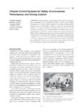
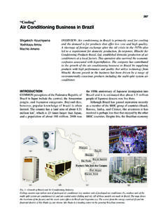
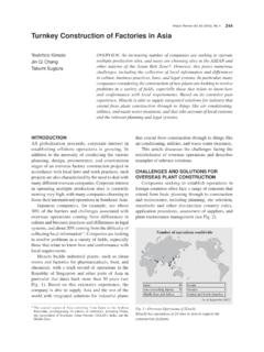
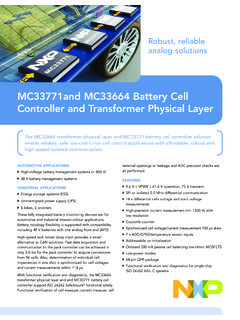
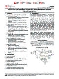
5 However, during off-peak and other times when there are few trains able to take the regenerative Energy produced during braking, this Energy has nowhere to go. This regenerative electric powerChargingElectric powerstorage unitElectric powerstorage unitTo other trainWaysideinstallationInstallationin trainFig. 1 Absorption of regenerative Electric electric power that cannot be returned to the power line is collected in a Storage battery. The collected Energy is then reused in the next acceleration to reduce the power consumption of the Storage System for Effective Use of regenerative Energy in electrified railways 34 regenerative brake with Effective speed extended (2) functionHitachi has developed the regenerative brake with Effective speed extended function as a solution to the problem of limits on performance due to motor characteristics.
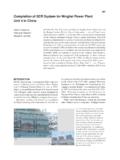
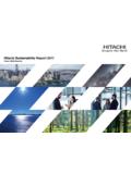
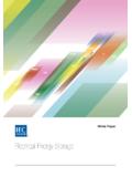
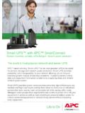
6 This function extends the operating range of the regenerative brake into higher speeds by using the Storage battery to boost the DC voltage of the inverter and increase the output of the electric motor, inverter, and so on without changing the level of the current flowing through each component, thereby shifting upwards the top speed of the V/F (voltage/frequency) range in which full regeneration is possible, as shown in Fig. Regeneration ManagementHitachi has developed an efficient regeneration management System to implement the absorption of regenerative electric power function and regenerative brake with Effective speed extended function in such is called regenerative braking under light load conditions.
7 As this causes the filter condenser voltage to rise, the light load regeneration control implemented on the inverter to suppress this rise operates to throttle back the regenerative current. Although the light load regeneration control suppresses the rise in the filter condenser voltage, in doing so it reduces the effectiveness of the regenerative brake which means it must be augmented by the air brake, reducing the regenerative i m i t s o n p e r f o r m a n c e d u e t o m o t o r (2) characteristicsThe Energy savings are maximized if regenerative braking can provide all of the braking Energy needed to decelerate to a halt. At higher speeds, however, the amount of regenerative braking is limited by the motor output characteristics.
8 As the additional required braking not able to be supplied by regenerative braking in this high speed range is provided instead by the air brake, the Energy -saving benefits are reduced ( limits on performance due to motor characteristics ).Proposed SolutionsAbsor pt ion of regenerat ive ele ct r ic power (1) functionHitachi has developed the absorption of regenerative electric power function as a solution to the problem of regenerative braking under light load conditions. When no other trains are available to make use of the regenerative Energy , the Energy is collected in a Storage battery so that it can be reused for acceleration (see Fig. 1). There are two options for locating the electric power Storage unit: one in which it is installed in the train and the other in which it is installed by the 2 regenerative Brake Storage battery extends the top speed of the operating range for regenerative braking by boosting the DC (direct current) voltage of the inverter and increasing the output of the motor, inverter, and other top speedSpeedRegenerative braking(1)(2)(2) regenerative brake with Effective speed extended functionRequired brakingExtended speed rangefor full regeneration(1) Previous operationV/F: voltage/frequencyFig.
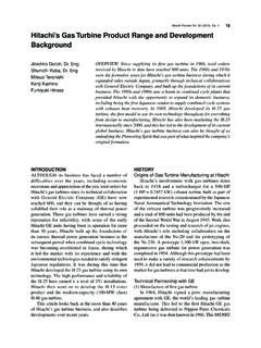
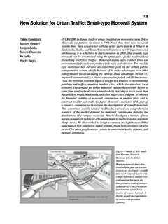
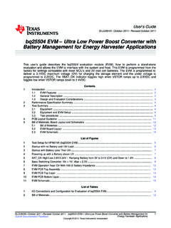
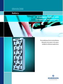
9 3 Outline of Efficient Regeneration System regenerative power absorption System is installed either in the train or on the wayside. When the regenerative brake with Effective speed extended function operates, an electric power Storage unit is inserted in series at the negative input terminal of the inverter.(a) Wayside installation of regenerative power absorption System (wayside installation)Power linevoltageRegenerative powerabsorption systemRegenerative powerabsorption systemRegenerative brake witheffective speed extendedRegenerative brake witheffective speed extendedRegenerative brake witheffective speed extendedRegenerative brake witheffective speed extendedCHPCHPCHPCHPFCFCFLFLMMMMVVVFVVVF S toragebatteryStoragebatteryStoragebatter yStoragebattery(installed in train)(b) regenerative power absorption System installed in trainCHP: chopper FL: filter reactor FC: filter condenser VVVF: variable voltage variable frequency MM: main motorHitachi Review Vol.
10 59 (2010), No. 1 35 a way that they operate appropriately. Fig. 3 shows an outline of how the equipment high-speed electric braking System used to implement the regenerative brake with Effective speed extended function increases the total voltage across the inverter by the amount of the battery voltage ( V) by inserting an electric power Storage unit in series between ground and the negative input terminal of the inverter to lower the voltage at the negative input terminal of the inverter by the battery voltage amount ( V) relative to the ground voltage. The chopper can vary this additional voltage continuously between 0 V a nd t he bat ter y volt age ( V) to ensure that the voltage of the filter condenser remains at its designated the System for absorbing regenerative power is located in the train, a Storage battery is inserted in parallel with the main circuit of the inverter via a step-up/step-down chopper.