Transcription of Engineering & Design Data - Spears Manufacturing, PVC ...
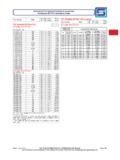
1 7 Water VelocitiesVelocities for water in feet per second at different GPM's and pipe inside diameters can be calculated as follows:Where: V = velocity in feet per secondG = gallons per minuteA = inside cross sectional area in square inchesCAUTION: Flow velocities in excess of feet per second are not recommended for closed-end systems. Contact Spears Technical Services for additional & Design Data FLOW VELOCITY & FRICTION LOSSF riction Loss Through FittingsFriction loss through fittings is expressed in equivalent feet of the same pipe size and schedule for the system flow rate.
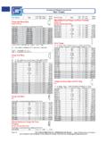
2 Schedule 40 head loss per 100' values are usually used for other wall thicknesses and standard iron pipe size Friction Loss for pvc and CPVC Fittings in Equivalent Feet of Straight Run PipeNote: Values 10"-24": Approximate values from Valves for Select Spears Valves and StrainersPressure Drop In Valves & StrainersPressure drop calculations can be made for valves and strainers for different fl uids, fl ow rates, and sizes using the CV values and the following equation:Where:P = Pressure drop in PSI; feet of water = PSI.
3 4332G = Gallons per minuteCV = Gallons per minute water per 1 PSI pressure dropSg = Specifi c gravity of liquid (water = 1)P = (G)2 (Sg) (CV)2V = .3208 G AFriction Loss Through PipeThe Hazen-Williams equation below is widely used to calculate friction loss for water through PVC and CPVC pipe f = .2083 x (100) x C : f = friction head of feet of water per 100' for the specific pipe size and C = a constant for internal pipe roughness. 150 is the commonly accepted value for pvc and CPVC pipe . G = flow rate of gallons per minute ( gallons). di = inside diameter of pipe in Size1/23/411-1/41-1/222-1/234681012 True Union 2000 Ball Valve12963120243357599856141628651952--- ---Single Entry Ball Valve13876146292412720--16603104-------- True Union 2000 Ball Check Valve(90 - Full Open)--------811091923454111125224944406 309Y-Check (12 Mesh-Clean) Strainer (Clean)
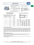
4 " 1- Full Port Ball Valve Cv based on equivalent length of Schedule 80 pipe8 Engineering & Design DataHead Loss Characteristics of Water Flow Through Rigid Plastic pipe NomographThe nomograph provides approximate values for water fl ow, head loss and water velocity for a wide range of plastic pipe sizes. Two known variables must be used to obtain the other variables by lining up the values on the scales using a ruler or straight edge. Flow velocities in excess of feet per second are not recommended.:DWHU IORZ LQ JDOORQV SHU PLQXWH,QVLGH GLDPHWHU RI SLSH LQ LQFKHV+HDG ORVV LQ 36, SHU IW RI SLSH+HDG ORVV LQ IHHW SHU IW RI SLSH:DWHU YHORFLW\ LQ IHHW SHU VHFRQG 9 NOTE: Spears recommends that Flow Velocities be maintained at or below 5 feet per second in large diameter piping systems ( 6" diameter and larger) to minimize the potential for hydraulic shock.
5 Refer to Spears Engineering section entitled "Hydraulic Shock" for additional information. Friction loss data based on utilizing mean wall dimensions to determine average ID; actual ID may vary. FLOW VELOCITY & FRICTION LOSS Engineering & Design DataGPM1-1/2" 2" 2-1/2" 3" 4" 5" 6" GPM2 2 5 5 7 7 10
6 10 15 15 20 20 25 25 30 30 35 35 40 40 45
7 45 50 50 60 60 70 70 75 75 80 80 90
8 90 100 100 125 125 150 150 175 175 200 200 250 250 300 300 350 350
9 400 400 450 450 500 500 SCHEDULE 40 Flow Rate (Gallons/ Minute) Flow Velocity (ft/sec.) Friction Loss ( 100ft) Friction Loss (psi/ 100ft) Flow Velocity (ft/sec.) Friction Loss ( 100ft) Friction Loss (psi/ 100ft) Flow Velocity (ft/sec.) Friction Loss ( 100ft) Friction Loss (psi/ 100ft) Flow Velocity (ft/sec.) Friction Loss ( 100ft) Friction Loss (psi/ 100ft) Flow Velocity (ft/sec.)
10 Friction Loss ( 100ft) Friction Loss (psi/ 100ft) Flow Velocity (ft/sec.) Friction Loss ( 100ft) Friction Loss (psi/ 100ft) Flow Velocity (ft/sec.) Friction Loss ( 100ft) Friction Loss (psi/ 100ft) Flow Rate (Gallons/ Minute) GPM1/8" 1/4" 3/8" 1/2" 3/4" 1" 1-1/4" 1