Transcription of Engineering & Design: Geometric Dimensioning SECTION 5
1 5-1 NADCA Product Specifi cation Standards for Die Castings / 2006 Engineering & Design: Geometric Dimensioning5 SECTION5 SECTION ContentsNADCA Introduction 5-22 What is GD&T?5-23 Why Should GD&T be Used?5-34 Datum Reference Frame5- , Secondary, Tertiary Features & Feature Vs. Datum Plane Vs. Datum Target Sizes & Locations5-65 Feature Control Frame5-66 Rule #1 Taylor Principle (Envelope Principle)5-77GD&T Symbols/Meanings5-88 Material Material Condition (MMC) Material Condition (LMC) of Feature Size (RFS)5-109 Location & Symmetry Tolerances5-1310 Profi le Tolerance5-1411 Run Out Tolerances5-1812 Orienta t ion Tolerances5 -1913 Form Tolerances5 S t ra igh t n e s s5 -2113.
2 2 Fl a t n e s s5 Circulatity (Roundness)5-2313. 4 Cy l i n dr ic i t y5 -2314 Conversion Charts5 Conversion of Position (Cylindrical) Tolerance Zones to/from Coordinate Tolerance Conversion of Position Tolerance Zone to/from Coordinate Tolerance Conversion of Coordinate Measurements to Position Location Measurements5-335-2 NADCA Product Specifi cation Standards for Die Castings / 2006 Engineering & Design: Geometric Dimensioning1 IntroductionThe concept of Geometric Dimensioning and tolerancing (GD&T) was introduced by Stanley Parker from Scotland in the late 1930 s.
3 However it was not used to any degree until World War II (WW II) because until then the vast majority of products were made in-house. The designer could discuss with the manufacturing personnel (die designer, foundry foreman, machinist, and inspectors) what features were to be contacted to establish the so called centerlines that were used on the drawing to locate features such as holes and keyways. Also when two (2) or more features were shown coaxial or symmetrical around these centerlines , the questions that needed to be answered by the designer was, how concentric or symmetrical do these features have to be to each other ?
4 During WW II companies had to farm out parts because of the quantities/schedules. This meant the new manufacturer had to interpret the drawing hence the centerlines were often established by contacting features that were not functional or important and features produced from these incorrect centerlines were not at the location required. The parts did not assemble and/or did not function properly hence had to be fi xed or scrapped. GD&T was the solution to this major problem. GD&T provides a designer the tools to have clear, concise, and consistent instructions as to what is required.
5 It eliminates ambiguities hence everyone that is involved with the part will not have to interpret the Dimensioning . 2 What is GD&T?It is compilation of symbols and rules that effi ciently describe and control Dimensioning & tolerancing for all drawings (castings, machined components,etc.). It is documented in ASME which has the symbols, rules, and simple examples. Also ASME has guidance for casting and forging Why should GD&T be used? a. It is a simple and effi cient method for describing the tolerancing mandated by the designer of the It eliminates ambiguities as to what Datum features are to be contacted to establish the Datum planes and/or Datum axis that are to be used for locating other features.
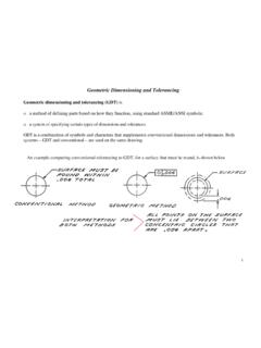
6 All inspection will result in the same result the dimension is within or out of tolerance. Fig. 5-1 illustrates a simple example of ambiguities associated with the old type drawing. Fig. 5-2 illustrates the same example with GD& It simplifi es inspection because hard gages can often be utilized and inspection fi xtures are often mandated which simplifi es inspection for production It forces the designer to totally consider function, manufacturing process, and inspection methods. The result is larger tolerances that guarantee function, but reduce manufacturing & inspection costs.
7 Also the bonus or extra tolerance for certain conditions can result in signifi cant production cost savings. In addition the time to analyze whether a missed dimen-sion is acceptable is dramatically Product Specifi cation Standards for Die Castings / 2006 Engineering & Design: Geometric Dimensioning5 Fig. 5-1 OLD Drawing without GD& 5-2 NEW Drawing with GD& :1) What is the relationship (coaxiality tolerance) between the and the ) Which feature ( or ) is to be used for measuring (locating) the .500 .005 dimension for locating the .120 hole?Questions asked in Fig.
8 5-1 answered:1) The axis of the has to be coaxial with the axis of the within a tolerance zone that is a .005 if the is which is the ) The is the feature to be used for measuring the .500 dimension for locating the hole. The tolerance for locating the .120 hole is a of .014 (the diagonal of the rectangular tolerance zone shown in Fig. 5-1) when the hole is a MMC ( .120).5-4 NADCA Product Specifi cation Standards for Die Castings / 2006 Engineering & Design: Geometric DimensioningFig. 5-3 Primary, secondary, tertiary features & datum Datum Reference Frame (DRF):The DRF is probably the most important concept of GD&T.
9 In order to manufacture and/or inspect a part to a drawing , the three (3) plane concept is necessary. Three (3) mutually perpendicular (exactly 90 to each other) and perfect planes need to be created to measure from. In GD&T this is called Datum Reference Frame whereas in mathematics it is the Cartesian coordinate system invented by Rene Descartes in France (1596-1650). Often one would express this concept as the need to establish the X,Y, and Z coordinates. The DRF is created by so-called Datum Simulators which are the manufacturing, processing, and inspection equipment such as surface plate, a collet, a three jaw chuck, a gage pin, etc.
10 The DRF simulators provide the origin of dimensional relationships. They contact the features (named Datum Features) which of course are not perfect hence measurements from simulators (which are nearly perfect) provides accurate values and they stabilize the part so that when the manufacturer inspects the part and the customer inspects the part they both get the same answer. Also if the part is contacted during the initial manufacturing setup in the same manner as when it is inspected, a layout for assuring machining stock is not required. The fi nal result (assuming the processing equipment is suitable for the tolerancing specifi ed) will be Primary, Secondary, and Tertiary Features & Datums: The primary is the fi rst feature contacted (minimum contact at 3 points), the secondary feature is the second feature contacted (minimum contact at 2 points), and the tertiary is the third feature contacted (minimum contact at 1 point).