Transcription of Engineering Aspects of Reverse Osmosis Module Design
1 Engineering Aspects of Reverse Osmosis Module Design Authors: Jon Johnson +, Markus Busch ++ + Research Specialist, Research and Development, Dow Water & Process Solutions ++ Global Desalination Application Specialist, Dow Water & Process Solutions Abstract During the half century of development from a laboratory discovery to plants capable of producing up to half a million tons of desalinated seawater per day, Reverse Osmosis (RO) technology has undergone rapid transition. This transition process has caused signification transformation and consolidation in membrane chemistry, Module Design , and RO plant configuration and operation. From the early days, when cellulose acetate membranes were used in hollow fiber Module configuration, technology has transitioned to thin film composite polyamide flat-sheet membranes in a spiral wound configuration.
2 Early elements about 4-inches in diameter during the early 70s displayed flow rates approaching 250 L/h and sodium chloride rejection of about percent. One of today s 16-inch diameter elements is capable of delivering 15-30 times more permeate (4000-8000 L/h) with 5 to 8 times less salt passage (hence a rejection rate of percent or higher). This paper focuses on the transition process in RO Module configuration, and how it helped to achieve these performance improvements. An introduction is provided to the two main Module configurations present in the early days, hollow fiber and spiral wound and the convergence to spiral wound designs is described as well. The development and current state of the art of the spiral wound element is then reviewed in more detail, focusing on membrane properties (briefly), membrane sheet placement (sheet length and quantity), the changes in materials used ( feed and permeate spacers), element size (most notably diameter), element connection systems (interconnectors versus interlocking systems).
3 The paper concludes with some future perspectives, describing areas for further improvement. Tel. + Fax. +31-152-616-289 THE EARLY HISTORY OF Reverse Osmosis Module Design Reverse Osmosis Module Design and Engineering emerged with membrane technology evolution. In order to understand Module Design , first membrane configuration needs to be explored, since the Module Design is always tailored according to the membrane characteristics. There is a significant difference between membrane chemistries (most important ones being cellulose acetate and thin film composite with polyamide barrier layer), and more importantly, between the different membrane configurations (hollow fine fiber and flat sheet). Therefore, before looking into detail on the Module configuration, the membrane development needs to be considered.
4 The invention of RO desalination and first applications After Schoenbein succeeded in the synthesis of nitrocellulose (1845) and Fick performed diffusion tests with nitrocellulose sheets (1855), more than 100 years had to pass before Ried and Breton succeeded in the demonstration of Reverse Osmosis desalination with cellulose acetate film (1959) and Loeb and Sourirajan developed asymmetric cellulose acetate membranes, which were the base for the first real world applications of Reverse Osmosis . North Star, the predecessor of FilmTec, initially used cellulose tri-acetate as separating layer in a thin film composite flat sheet configuration (1964), but then switched to a polyamide barrier separating layer. The Dow Chemical Company ( Dow ) developed a cellulose tri-acetate membrane (1971) in hollow fine fiber configuration later commercialized the DOWEX range of HF modules (1971).
5 Toyobo followed with a similar hollow fiber cellulose acetate membrane in 1978. DuPont used a different membrane chemistry, initially nylon (1967), later aromatic polyamide (1969). Of the three producers of hollow fine fiber modules, the Permasep B-9 and later B-10 Permeator from DuPont became the leading element in the market in the 1980s and early 1990s. The early cellulose acetate hollow fine fiber modules were capable of withstanding the pressures required for seawater Reverse Osmosis and one of the key features of the CTA fiber was that it had a relatively high level of tolerance to the presence of free chlorine at a time when competitive HF products from DuPont and spiral wound elements from Fluid Systems had very low, effectively zero tolerance to the presence of free chlorine.
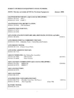
6 Due its market dominance in the early years of RO desalination, the Dupont Permeator is selected as typical example to illustrate the early hollow fine fiber Module configuration and the performance of the initial seawater desalination systems with this concept. The early years of RO desalination the hollow fine fiber DuPont Permeator The DuPont membrane was an asymmetric fiber with 42 m inner diameter and 85 m outer diameter, of which m was dense skin layer and remainder porous support, made from aromatic polyamide (aramide). A typical 10-inch diameter Module , contained about 4,400,000 fibers. These were built into a Module by applying epoxy adhesive to one side during bundling and after winding became the tube sheet. The other end of the fiber bundle was sealed with epoxy to form the nub which prevents short-circuiting of the feed stream to the brine outlet [DuPont, 1983].
7 The Module and RO process is shown in Figure 1. Figure 1: Hollow fine fiber Module and process [DuPont, 1983] The first Permasep Hollow Fiber B-10 Permeators from DuPont were introduced commercially in Europe in 1974. These were 4 elements which had a capacity of m3/d (1,500 gpd) and a salt rejection of percent under standard test conditions (30,000 mg/L NaCl, 55bar/800 psi, 30 percent recovery, 25 C) [Cicera & Shields 1997]. Between 1974 and 1997 DuPont continuously improved the Design and the performance of their HF elements. In 1992 the double-bundled B-10 TWIN Permeator was introduced. The model 6880T with an aramide HF membrane had a capacity of m3/d (16,000 gpd) and a salt rejection of percent (std. cond.: 35,000 mg/L NaCl, 69 bar / 1000 psi, 35 percent recovery, 25 C).
8 Shortly before DuPont terminated membrane production the Hollow-Fiber Cartridge was introduced. The model SW-H-8540, Single Cartridge had a nominal 8 -inch diameter by 40-inch length with a capacity of m3/d (8,000 gpd) and percent salt rejection (std. cond.: 35,000 mg/L NaCl, 69 bar/1000 psi, 35 percent recovery, 25 C) [Eckman et al 1997]. Between 1983 and 1997, for a typical sea water with a temperature between 17 38 C and a salt content of 36,000 45,000 mg/L, the major Design characteristics of a single pass Permasep SWRO (sea water Reverse Osmosis ) plant with a B10-Permeator were [Andrews & Bergman 1983, Eckman et al 1994, Pohland et al 1994, Hamida et al 1997, Barendsen & Moch 1995]: Recovery: 30 % 50 % Feed pressure: 1,000 1,200 psi (69 bar) Permeate quality: < 500 mg/L Energy consumption: kWh/m3 The shift to spiral wound modules At the time when Permasep HF-Permeators for desalination of seawater were introduced into the market in the 1970 s they had some advantages compared to seawater spiral wound elements which explain their success in the RO-market at this time [Moch, 1992].
9 Permasep HF-Permeators are self supporting membranes. This simplified the hardware for fabrication compared to flat-sheet membranes which have to be assembled with spacers and supports. In addition the hollow fibers were able to operate up to (1,200 psi), which allowed to reach relatively high recoveries, like 60 percent at 25 C and 38,000 mg/L feed TDS (total dissolved solids). At a similar specific permeate flux (flow per membrane area), a conventional flat sheet membrane needed only about 50 percent of the feed pressure of a hollow fiber. This relatively low permeability of a single fiber in comparison to a flat sheet membrane was compensated by the Permasep HF Permeator with the extremely high area per Permeator (Single Cartridge : > 372 m2, (4,000 ft2)). This high area allowed working at relatively low fluxes.
10 This reduces concentration polarization and the risk of scaling. The relatively low concentration polarization also improved the rejection of the Permeator. A major disadvantage of the Permasep HF Permeator was its tendency to foul and plug due to low free space between the hollow fibers and due to dead zones in the Permeator [Moch, 1992]. In addition fouling and scaling was difficult to remove due to the low cross flow velocities and a relatively limited pH-range (4 11). These constraints required a high RO-feed water quality (SDI < 3) which resulted in higher pretreatment costs and some operational difficulties. To keep the rejection of the Permasep HF Permeator constant it generally had to be coated by PT-A (poly vinyl methyl ether) and PT-B (tannic acid) [Moch, 1992]. These chemicals had to be reapplied frequently, PT-B even after every membrane cleaning cycle.