Transcription of Engineering Drawing
1 Engineering Drawing Traditional Drawing Tools Drawing TOOLS 1. T-Square 2. Triangles Drawing TOOLS 3. Adhesive Tape 4. Pencils HB for thick line 2H for thin line Drawing TOOLS 5. Sandpaper 6. Compass Drawing TOOLS 7. Pencil Eraser 8. Erasing Shield Drawing TOOLS 9. Circle Template 10. Tissue paper Drawing TOOLS 11. Sharpener 12. Clean paper Drawing TOOLS Freehand Sketching Straight Line 1. Hold the pencil naturally. 2. Spot the beginning and end points. 3. Swing the pencil back and forth between the points, barely touching the paper until the direction is clearly established.
2 4. Draw the line firmly with a free and easy wrist-and-arm motion Horizontal line Vertical line Nearly vertical inclined line Nearly horizontal inclined line Small Circle Method 1 : Starting with a square 1. Lightly sketching the square and marking the mid-points. 2. Draw light diagonals and mark the estimated radius. 3. Draw the circle through the eight points. Step 1 Step 2 Step 3 Method 2 : Starting with center line Step 1 Step 2 Step 3 1. Lightly draw a center line. 2. Add light radial lines and mark the estimated radius. 3. Sketch the full circle.
3 Small Circle Arc Method 1 : Starting with a square Method 2 : Starting with a center line Basic Strokes Straight Slanted Curved Horizontal 1 1 2 3 Examples : Application of basic stroke I letter A letter 1 2 3 4 5 6 B letter Suggested Strokes Sequence Straight line letters Curved line letters Curved line letters & Numerals Upper-case letters & Numerals The text s body height is about 2/3 the height of a capital letter. Suggested Strokes Sequence Lower-case letters GOOD Not uniform in style. Not uniform in height. Not uniformly vertical or inclined.
4 Not uniform in thickness of stroke. Area between letters not uniform. Area between words not uniform. Example : Good and Poor Lettering Leave the space between words equal to the space requires for writing a letter O . Example Sentence Composition ALL DIMENSIONS ARE IN MILLIMETERS O O O O UNLESS OTHERWISE SPECIFIED. O GRAPHICS LANGUAGE 1. Try to write a description of this object. 2. Test your written description by having someone attempt to make a sketch from your description. Effectiveness of Graphics Language The word languages are inadequate for describing the size, shape and features completely as well as concisely.
5 You can easily understand that .. Graphic language use lines to represent the surfaces, edges and contours of objects. A Drawing can be done using freehand, instruments or computer methods. Composition of Graphic Language The language is known as Drawing or drafting . Freehand Drawing The lines are sketched without using instruments other than pencils and erasers. Example Instrument Drawing Instruments are used to draw straight lines, circles, and curves concisely and accurately. Thus, the drawings are usually made to scale. Example Computer Drawing The drawings are usually made by commercial software such as AutoCAD, solid works etc.
6 Example Architectural Graphics Elements Drawing comprises of graphics language and word language. Graphics language Describe a shape (mainly). Word language Describe size, location and specification of the object. Basic Knowledge for Drafting Graphics language Word language Line types Geometric construction Lettering projection method projection METHOD projection METHOD Perspective Oblique Orthographic Axonometric Multiview Parallel projection THEORY The projection theory is based on two variables: 1) Line of sight 2) Plane of projection (image plane or picture plane) The projection theory is used to graphically represent 3-D objects on 2-D media (paper, computer screen).
7 Line of sight is an imaginary ray of light between an observer s eye and an object. Line of sight Parallel projection Line of sight Perspective projection There are 2 types of LOS : parallel converge and Plane of projection is an imaginary flat plane which the image is created. The image is produced by connecting the points where the LOS pierce the projection plane. Parallel projection Perspective projection Plane of projection Plane of projection Disadvantage of Perspective projection 1) It is difficult to create. 2) It does not reveal exact shape and size.
8 Width is distorted Orthographic projection 5 Orthographic projection is a parallel projection technique in which the parallel lines of sight are perpendicular to the projection plane MEANING Object views from top projection plane 1 2 3 4 5 1 2 3 4 ORTHOGRAPHIC VIEW Orthographic view depends on relative position of the object to the line of sight. Two dimensions of an object is shown. Three dimensions of an object is shown. Rotate Tilt More than one view is needed to represent the object. Multiview Drawing Axonometric Drawing Orthographic projection technique can produce either 1.
9 Multiview Drawing that each view show an object in two dimensions. 2. Axonometric Drawing that show all three dimensions of an object in one view. Both Drawing types are used in technical Drawing for communication. NOTES ORTHOGRAPHIC VIEW Axonometric ( isometric ) Drawing Easy to understand Right angle becomes obtuse angle. Circular hole becomes ellipse. Distortions of shape and size in isometric Drawing Advantage Disadvantage Shape and angle distortion Example Types of Axonometrics Multiview Drawing It represents accurate shape and size.
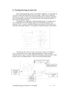
10 Advantage Disadvantage Require practice in writing and reading. Multiviews Drawing (2-view Drawing ) Example The Glass Box Approach Orthographic projection Opening the Box Final Views Six Orthographic Views Laying Out All Six Views Three Primary Views Construction of Views Third-angle projection First-angle projection First and Third Angle Projections First Angle International Third Angle Basic Line Types Types of Lines Appearance Name according to application Continuous thick line Visible line Continuous thin line Dimension line Extension line Leader line Dash thick line Hidden line Chain thin line Center line Visible lines