Transcription of Engineering Formulas - MasterDrives
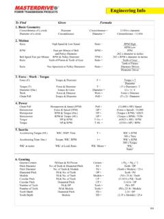
1 111 Engineering Info1. Basic Geometry Circumference of a circle Diameter Circumference = x diameter Diameter of a circle Circumference Diameter = Circumference / Motion Ratio High Speed & Low Speed Ratio = RPM High RPM Low RPM Feet per Minute of Belt RPM = FPM and Pulley Diameter .262 x diameter in inches Belt Speed Feet per Minute RPM & Pulley Diameter FPM = .262 x RPM x diameter in inches Ratio Teeth of Pinion & Teeth of Gear Ratio = Teeth of Gear Teeth of Pinion Ratio Two Sprockets or Pulley Diameters Ratio = Diameter Driven Diameter Driver3. Force - Work - Torque Force (F) Torque & Diameter F = Torque x 2 Diameter Torque (T) Force & Diameter T = ( F x Diameter) / 2 Diameter (Dia.) Torque & Force Diameter = (2 x T) / F Work Force & Distance Work = Force x Distance Chain Pull Torque & Diameter Pull = (T x 2) / Diameter4.
2 Power Chain Pull Horsepower & Speed (FPM) Pull = (33,000 x HP)/ Speed Horsepower Force & Speed (FPM) HP = (Force x Speed) / 33,000 Horsepower RPM & Torque (#in.) HP = (Torque x RPM) / 63025 Horsepower RPM & Torque (#ft.) HP = (Torque x RPM) / 5250 Torque HP & RPM T #in. = (63025 x HP) / RPM Torque HP & RPM T #ft. = (5250 x HP) / RPM5. Inertia Accelerating Torque (#ft.) WK2, RMP, Time T = WK2 x RPM 308 x Time Accelerating Time (Sec.) Torque, WK2, RPM t = WK2 x RPM 308 x Torque WK2 at motor WK2 at Load, Ratio WK2 Motor = WK2 Ratio26. Gearing Gearset Centers Pd Gear & Pd Pinion Centers = ( PdG + PdP ) / 2 Pitch Diameter No. of Teeth & Diametral Pitch Pd = Teeth / DP Pitch Diameter No. of Teeth & Module Pd = (Teeth x Module) / Diametral Pitch Pd & No.
3 Of Teeth DP = Teeth / Pd Module Pd & No. of Teeth Module = (Pd x ) / Teeth Circular Pitch Pd & No. of Teeth CP = ( x Pd) / Teeth Circular Pitch Diametral Pitch CP = / DP Number of Teeth Pd & DP Teeth = Pd x DP Number of Teeth Pd & Module Teeth = (Pd x ) / Module Tooth Depth Diametral Pitch TD = / DP Tooth Depth Module TD = ( x Module) / To Find Given Formula112 Engineering Info To Find Given Formula7. Belting Effective Tension T1 and T2 Te = T1 - T2 Effective Tension HP, RPM, Pulley Radius Te = 63025 x HP RPM x R Effective Tension Torque, Pulley Radius Te = Torque / R Effective Tension Horsepower, Belt Velocity (FPM) Te = (HP x 33000) / FPM Total Load T1 & T2 TL = T1 + T28. Overhung Load Overhung Load Torque, Diameter OHL = (T x 2) / Diameter Overhung Load Effective Tension, Belt Factor OHL = Te x f f = V-Belts f = flat belts Overhung Load Horsepower, Speed (RPM) OHL = 126000 x f x HP Diameter, factor Diameter x RPM f = chain f = gear drives f = V-belts f = flat belts Overhung Load Weight OHL = Weight9.
4 Electricity Motor Speed (RPM) Number of Poles RPM = 120 x HZ No. of Poles Horsepower Single Phase or Volts, Amps, Power factor HP = Volts x Amps x Pf x Eff. Direct Current Motor Efficiency 746 Horsepower 3 Phase Motor Volts, Amps, Power factor HP = Volts x Amps x x Pf x Eff. Efficiency 746 Horsepower Watts HP = Watts / 746 Horsepower Kilowatts HP = KW / .746 Motor Power (Watts), Single Phase Volts, Amps, Pf, Eff. Watts = V x Amps x Pf x Eff. Motor Power (Watts), 3 Phase Volts, Amps, Pf, Eff. Watts = x V x Amps x Pf x Temperature Degrees Fahrenheit Degrees Centigrade oF = ( x o C) + 32 Degrees Centigrade Degrees Fahrenheit oC = 5/9 (oF - 32)11. Metric Conversions Inches x = Millimeters Millimeter x .0394 = inches Pounds x .455 = Kilograms Kilogram x = pounds Gallons x = Liters Liter x.
5 264 = Gallon Pounds (Force ) x = Newtons Newtons x .2246 = Pounds (Force) Pounds inches x .113 = Newton Meters Newton Meters x = Pound-ins. Horsepower x .746 = Kilowatts Kilowatts x = Horsepower Pounds/in2 (psi) x .0069 = Newtons/mm2 Newton /mm2 x 145 = Pounds/in2 BTU x .00029 = Kilowatt Hours Kilowatt Hours x 3415 = BTU s113 To Find Given Formula7. Belting Effective Tension T1 and T2 Te = T1 - T2 Effective Tension HP, RPM, Pulley Radius Te = 63025 x HP RPM x R Effective Tension Torque, Pulley Radius Te = Torque / R Effective Tension Horsepower, Belt Velocity (FPM) Te = (HP x 33000) / FPM Total Load T1 & T2 TL = T1 + T28. Overhung Load Overhung Load Torque, Diameter OHL = (T x 2) / Diameter Overhung Load Effective Tension, Belt Factor OHL = Te x f f = V-Belts f = flat belts Overhung Load Horsepower, Speed (RPM) OHL = 126000 x f x HP Diameter, factor Diameter x RPM f = chain f = gear drives f = V-belts f = flat belts Overhung Load Weight OHL = Weight9.
6 Electricity Motor Speed (RPM) Number of Poles RPM = 120 x HZ No. of Poles Horsepower Single Phase or Volts, Amps, Power factor HP = Volts x Amps x Pf x Eff. Direct Current Motor Efficiency 746 Horsepower 3 Phase Motor Volts, Amps, Power factor HP = Volts x Amps x x Pf x Eff. Efficiency 746 Horsepower Watts HP = Watts / 746 Horsepower Kilowatts HP = KW / .746 Motor Power (Watts), Single Phase Volts, Amps, Pf, Eff. Watts = V x Amps x Pf x Eff. Motor Power (Watts), 3 Phase Volts, Amps, Pf, Eff. Watts = x V x Amps x Pf x Temperature Degrees Fahrenheit Degrees Centigrade oF = ( x o C) + 32 Degrees Centigrade Degrees Fahrenheit oC = 5/9 (oF - 32)11. Metric Conversions Inches x = Millimeters Millimeter x .0394 = inches Pounds x .455 = Kilograms Kilogram x = pounds Gallons x = Liters Liter x.
7 264 = Gallon Pounds (Force ) x = Newtons Newtons x .2246 = Pounds (Force) Pounds inches x .113 = Newton Meters Newton Meters x = Pound-ins. Horsepower x .746 = Kilowatts Kilowatts x = Horsepower Pounds/in2 (psi) x .0069 = Newtons/mm2 Newton /mm2 x 145 = Pounds/in2 BTU x .00029 = Kilowatt Hours Kilowatt Hours x 3415 = BTU sEngineering Info Engineering Calculations Quick Reference Guide Torque (Torque, Pound-inches) (RPM)Horsepower = 63,025 (Torque, Pound-feet) (RPM)Horsepower = 5,252 Torque Required to Accelerate or Decelerate a FlywheelThe torque required to uniformly accelerate or decelerate a sheave, pulley or flywheel can be calcu-lated as follows: .03908 x N x W x R2.
8 003257 x N x W x R2 Torque (in. lbs.) = t Torque (ft. lbs.) = t N = Difference between initial and final RPM. W = Weight of rim in pounds. R = Mean Radius of Sheave Rim, Pulley or Flywheel in feet. t = Time required to effect speed change, in for WR2 Calculations Outside Diameter (D0) Add to PD Outside Minus Inside Diameter (D1)Groove Pitch Diameter to find Do Diameter (in) for Standard Sheaves Y Z3V - - up to .113 .30 - - to .113 .30 - - to .113 .305V - - up to .320 .50 - - to .320 .50 - - to .320 .508V - - up to .885 .80 - - to .885 .80 - - & up .885 .80A Multi-Duty All .75 - .377 .50B Multi-Duty All .35 - .377 .50A All .25 - .238 .40B All .35 - .384 .50C Up to .40 - .696 .65C to .40 - .696 .68D Up to.
9 60 - .90D to .60 - .90 E (Special) .80 - Flywheel Effect, WR2 (Do4 - D14) NY (Do - Z)3WR2 = 1000 1000 for gray iron. Multiply by for : D0 = Outside diameter of rim, inches. D1 = Inside diameter of rim, inches. F = Face width of rim, inches N = Number of grooves Y = Groove constant from table Z = Groove constant from table114V-Belt Drive FactorsArc of Contact Correction Factors G and R .00 1800 .80 1330 .87 .917 .10 1740 .99 .999 .90 1270 .85 .893 .20 1690 .97 .995 1200 .82 .866 .30 1630 .96 .989 1130 .80 .835 .40 1570 .94 .980 1060 .77 .800 .50 1510 .93 .968 990 .73 .760 .60 1450 .91 .954 910 .70 .714 .70 1390 .89 .937 830 .65 .661D = Diam. of large sheaveC= Center distanced = Diam. of small sheaveAllowable Sheave Rim SpeedCast Iron.
10 6,500 Ductile Iron ..8,000 Steel ..10,000 NOTE: Above rim speed values are maximum for normal considerations. In some cases, these values may be ex-ceeded. Consult factory and include complete detailsof proposed Load CalculationsTo find actual loads, it is necessary to know machine component weights and values of all other forces contributing to the load. Sometimes it becomes desirable to know the bearing load imposed by the V-belt drive alone. This can be done if you know bearing spacing with respect to the sheave center and shaft load and apply it to the formula :Short Cut Ways to Figure Pump Drives*D = Diameter of pump sheave*d = Diameter of engine sheaveSPM = Strokes Per MinuteRPM = Engine Speed in Revolutions Per MinuteR = Gear box ratio*C = Shaft center distance*Required values to determine belt lengthBelt length = 2C + (D+d) + (D-d)2 4CD = RPM x d SPM x Rd = SPM x R x D RPMSPM = RPM x d R x DRPM = SPM x R x D dR = RPM x d SPM x DOverhung Sheave Sheave Between BearingsLoad at B, lbs = Shaft Load x (a+b)