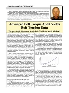
Transcription of Engineering Fundamentals of Threaded Fastener …
1 1 RS Technologies, a Division of PCB Load & torque , Inc. 24350 Indoplex Circle, Farmington Hills, MI 48335 USA Toll-Free in the USA 888-684-2894 Fax:716-684-0987 ISO9001 Certified A2LA Accredited to ISO17025 Engineering Fundamentals of Threaded Fastener Design and Analysis By Ralph S. Shoberg, , Director of Technology, PCB Load & torque , Inc. 2 RS Technologies, a Division of PCB Load & torque , Inc. 24350 Indoplex Circle, Farmington Hills, MI 48335 USA Toll-Free in the USA 888-684-2894 Fax:716-684-0987 ISO9001 Certified A2LA Accredited to ISO17025 Table of Contents Introduction: Engineering Fundamentals of the Tightening Process.
2 3 Energy 3 Modeling the Tightening 3 Where Does the torque Go? .. 4 Elastic torque -Tension Relationship .. 5 Stress/Strain vs. torque /Tension ..5 Correlation of Stress-Strain and Turn .. 6 Force-Deformation and torque -Angle Diagrams ..7 Preload-Preload Efficiency Factor ..7 torque -Tension Correlation Coefficient ..8 Thread/Underhead Friction Measurements .. 8 Automated Tightening Process .. 9 torque -Angle-Tension Control .. 9 Introduction .. 9 torque -Angle-Signature ..10 torque -Angle Signature Analysis.
3 11 Tightening Curve .. 12 Elastic Origin .. 12 Loosening Curve ..12 Beyond Yield .. 13 Loosening Tendencies .. 13 Accurate Measurement .. 13 torque -Angle Signature Analysis Summary ..14 Clamp Force/Strength Considerations .. 14 Modeling the Tightening Process ..14 torque -Tension Coefficient: Nut Factor, K .. 16 Experimental Determination of Friction Coefficients .. 17 Thread/Underhead Friction Coefficient Measurements .. 17 M-Alpha Diagram .. 18 FM-Alpha Diagram .. 19 Estimating the Tension-Angle Coefficient .. 20 Ultrasonic Stretch.
4 20 Strain-Gaged Bolt .. 20 Force Washer .. 21 Model-Calculation: Estimate of Angle-Tension Coefficient .. 21 Laboratory Measurement of Friction Coefficients .. 22 Material Property-Yield .. 23 torque -Angle Tension Control Summary .. 23 torque -Tension Audits .. 25 Introduction .. 25 Hand torque Audit-Tool torque Capability .. 26 Tool torque Capability/ISO 5393 .. 26 Release Angle-Tension Audit .. 26 Loosening-Embedment or Loss of Preload .. 29 Measurements Verify Fastener torque and Tension .. 29 Other Strategies .. 33 torque -Turn-To-Yield.
5 33 Prevailing torque Locknut Signature Analysis .. 33 Hand torque Tightness Quality Audits .. 33 Redefining The Audit .. 34 Hand torque Audit Qualification .. 36 Using torque Angle Records to Determine Joint Stiffness .. 36 Material Yield Point .. 38 Glossary of Important Terms .. 38 References .. 39 3 RS Technologies, a Division of PCB Load & torque , Inc. 24350 Indoplex Circle, Farmington Hills, MI 48335 USA Toll-Free in the USA 888-684-2894 Fax:716-684-0987 ISO9001 Certified A2LA Accredited to ISO17025 Introduction: Engineering Fundamentals of the Tightening Process The process of tightening Threaded Fastener assemblies, especially for critical bolted joints, involves controlling both input torque and angle of turn to achieve the desired result of proper preload of the bolted assembly.
6 Understanding the role of friction in both the underhead and Threaded contact zones is the key to defining the relationship between torque , angle, and tension. There can be as many as 200 or more factors that affect the tension created in a bolt when tightening torque is applied (refer to paragraph ). Fortunately, torque -angle signature curves can be obtained for most bolted joints. By combining the torque -angle curves with a few simple calculations and a basic understanding of the Engineering mechanics of Threaded fasteners, you can obtain the practical information needed to evaluate the characteristics of individual Fastener tightening processes. The torque -angle curves can also provide the necessary information to properly qualify the capability of tightening tools to properly tighten a given Fastener .
7 Energy Transfer Tightening Threaded fasteners is basically an energy transfer process as shown in Figure 1. The area under the torque -angle curve is proportional to the energy required to tighten the Fastener . Figure 1 Tightening Fasteners Transfers Energy Modeling the Tightening Process Achieving proper control of the tightening process is possible only if you understand the relationship between torque and turn in the development of tension. Before studying tightening methods, it is necessary to become familiar with what actually happens when a Fastener is tightened. The process of tightening a Fastener involves turning, advance of the lead screw, and torque , turning moment, so that preload, tension, is produced in the Fastener .
8 The desired result is a clamping force to hold components together. Figure 2. Four Zones of the Tightening Process The most general model of the torque -turn signature for the Fastener tightening process has four distinct zones as illustrated in Figure 2. The first zone is the rundown or prevailing torque zone that occurs before the Fastener head or nut contacts the bearing surface. The second zone is the alignment or snugging zone wherein the Fastener and joint mating surfaces are drawn into alignment to achieve a snug condition. 4 RS Technologies, a Division of PCB Load & torque , Inc. 24350 Indoplex Circle, Farmington Hills, MI 48335 USA Toll-Free in the USA 888-684-2894 Fax:716-684-0987 ISO9001 Certified A2LA Accredited to ISO17025 The third zone is the elastic clamping range, wherein the slope of the torque -angle curve is essentially constant.
9 The fourth zone is the post-yield zone, which begins with an inflection point at the end of the elastic range. Occasionally, this fourth zone can be due to yielding in the joint or gasket, or due to yield of the threads in the nut or clamped components or nut rather than to yield of the Fastener . NOTE: A more detailed discussion of the four tightening zones is presented in section In the special case where prevailing torque locking features are employed, the model includes an additional prevailing torque zone. In a more general sense, the prevailing torque can be the result of frictional drag on the shank or threads due to the misalignment of the parts, to chips or other foreign material in the threads, or due to out of tolerance threads with unintended interference.
10 The nonlinear alignment zone is a complex function of the process of drawing together of the mating threads, bending together of mating parts, and bending of the Fastener as a result of non-parallelism of the bearing surface to the Fastener underhead surface. These factors are referred to as macro effects. The alignment zone also has what is referred to as micro components. The micro effects include contact stress defections of plating and coatings as well as surface and thread deformations. These effects are illustrated in Figure 3. Figure 3. Alignment Zone Where Does the torque Go? The basic torque distribution for a Fastener is illustrated in Figure 4. The torque applied to a Fastener is absorbed in three main areas.