Transcription of Engineering Graphics Resources
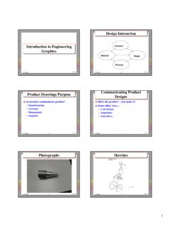
1 Engineering Graphics 4 unites (3 units of lecture and 1 unit of lab) Prerequisite: Trigonometry Course Description: This course covers the principles of Engineering drawings in visually communicating Engineering designs and an introduction to computer-aided design (CAD). Topics include the development of visualization skills; orthographic projections; mechanical dimensioning and tolerancing practices; and the Engineering design process. Assignments develop sketching and 2-D and 3-D CAD skills. The use of CAD software is an integral part of the course. Course Content: Engineering design Basic Engineering drawing concepts Visualization skills Use of Engineering /architect scales Multiview drawings Auxiliary Views Pictorial projections Section Views Dimensioning Tolerancing Threaded fastener terminology CAD: o 2D Construction and Editing Tools o 3D solid modeling Detail and Assembly Drawings Descriptive Geometry (optional) Student Learning Outcomes: At the conclusion of this course, the student should be able to: 1.
2 Apply rules of orthographic projection to create multiview drawings. 2. Create pictorials from orthographic views. 3. Use CAD software to create: 2D Engineering drawings, including working drawings and assembly drawings. 3D models and assemblies 4. Create auxiliary and section views of an object following correct conventions. 5. Apply standards of dimensioning and tolerancing to Engineering drawings. 6. Apply the Engineering design process to a design project. Engineering Graphics Resources Topic Lecture Videos Lecture Notes Lab Handouts Tutorials Homework Introduction to Graphics Sketching Basic 2D Construction Lecture 1 Lecture 1 Lab 1 Lab1-1 Lab1-2 HW 1 Engineering Geometry Construction and Editing Tools design Visualization Lecture 2 Lecture 3 Lecture 2 Lab 2 Lab 3 Lab2-1 Lab2-2 Lab2-3 Lab3-a Lab3-b HW 2 HW 3 Orthographic Views Lecture 4 Lecture 3 Lab 4 Lab 5 Lab4-a Lab4-b Lab5 HW 4 HW 5 Pictorial Projections.
3 Isometric, Oblique, and Perspective Sketches Lecture 5 Lecture 4 Lab 6 Lab7 Lab6-1 Lab6-2 Lab6-3 Lab7 HW 6 HW 7 Sectional Views Lecture 6 Lecture 5 Lab 8 Lab9 Lab8-a Lab8-b Lab9 HW 8 HW 9 Templates; Basic Dimensioning and Notes Lecture 7 Lecture 6 Lab 10 Lab10 HW 10 Auxiliary Views Lecture 8 Lecture 7 Lab 11 Lab 12 Lab11 Lab12 HW 11 HW 12 3-D Basics: Wireframe Modeling Descriptive Geometry Lecture 9 Lecture 10 Lecture 11 Lecture 8a Lecture 8b Lecture 8c Lab 13 Lab 14 Lab13 Lab14 HW 13 HW 14 Solid Modeling Descriptive Geometry Lecture 12 Lecture 13 Lecture 14 Lecture 9 Lecture 9b Lecture 10 Lab 15 Lab 16 Lab15 Lab16 HW 15 HW 16 Advanced Solid Features Working Drawings and Assemblies Lecture 15 Lecture 16 Lecture 11 Lab 17 Lab 18 Lab17 Lab18 HW 17 Geometric Dimensioning and Tolerancing Engineering design Process Lecture 17 Lecture 18 Lecture 12 Lecture 13 Lab 19 Lab19 HW 18
4 SolidWorks Parts SolidWorks Assemblies Lecture 19 Lecture 20 Lecture 14 Lecture 15 Lab 20 Lab 21 Lab20 HW19 SolidWorks Drawings More SolidWorks Techniques Animation with SolidWorks Lecture 21 Lecture 22 Lecture 16 Lecture 17 Lab 22 Lab 23 Lab 24 Lab 25 This material is based upon work supported by the National Science Foundation under Grant No. DUE 1430789. Any opinions expressed in this material are those of the author and do not necessarily reflect the views of the National Science Foundation (NSF).