Transcription of Engineering research project: methodology
1 Developed by Learning Advisers 1 Engineering research project: methodology Example: Describing the instrument design and development This study involved the analysis of data received from the 43-item MCAS, taken by maintenance personnel from 27 Navy and Marine Corps aviation units. The MCAS is a self-administered survey consisting of nine demographic and 43 maintenance-related items (see Appendix A). The demographic items are: 1) rank; 2) total years aviation maintenance experience; 3) work center; 4) primary shift; 5) current model aircraft; 6) status (active duty, drilling reservist or active reservist); 7) parent command; and 8) unit s location.
2 The maintenance items are grouped into the six HRO components: process auditing, reward system, quality, risk management, command and control, and communication/functional relationships. The MCAS utilizes a five-point Likert scale to capture participant responses: Strongly Disagree, Disagree, Neutral, Agree, and Strongly Agree (note: options of Not Applicable and Don t Know are also available). (Adapted from Hernandez 2001, p. 20) Example: Justifying your choices Radiographic techniques are the main non-invasive method used to determine .. The decision to use such techniques is in line with the aims of this project which are to.
3 The quantitative experimental techniques which will be used are laser doppler velocimetry (LDV) and particle image velocimetry (PIV).. The two most widely used media to record the light intensity maps of the flow fields are charge-coupled device (CCD) chips or the complementary metal-oxide semiconductor (CMOS) chips (Sherry 2012). The second advantage of using the multivariate method is .. Developed by Learning Advisers 2 Example: Acknowledging other possibilities The primary focus of this project is to .. While alternative methodologies have been used in the past to.
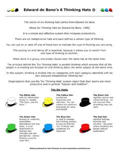
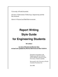
4 These are not considered appropriate for this study. These alternatives will be discussed in a later section, specifically in relation to why they are not considered feasible. Describing your data collection procedures Example: describing the research site A watershed on the Texas A&M University campus in College Station, Texas, is used to demonstrate HFR calculations for a realistic watershed and its use for storm-water management. Watershed D on the West Campus contributes to tributaries of White Creek, which is in the headwaters of the Brazos River (Figure 4). Tributary D cuts through the West Campus area, draining square kilometers through a natural open channel of km in length (Figure 5).
5 Soils in this area are clays and sandy clays with sand lens and are classified as Group D hydric soils, and the CN is 77 (City of Bryan/College Station 2008; Thompson 2005). The upper subwatershed of the watershed is densely occupied by commercial and university facilities, and the lower subwatershed is covered sparsely by urban land use. Because of increased development, erosion and stream bed degradation occurred in Tributary D (Figure 5). Gabions have been placed to alleviate increased velocities, and a detention pond has been recommended for further mitigation of increased storm-water runoff volumes (Thompson 2005).
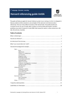
6 (Giacomoni et al. 2012, p. 102) Example: describing simulator instruments and procedures Figure 1 is a photograph image of the simulator used in this study. Controllers communicated via radio (voice communications) with pseudo-pilots, who were responsible for controlling all of the aircraft in the simulation. Pseudo-pilots were located in an isolated room adjacent to the tower simulator environment. The pseudo-pilots controlled aircraft via a customized Graphical User Interface (GUI), which sent commands to an application that managed all of the simulation displays. A head-mounted eye tracker (Applied Science Laboratories: Mobile Eye) was used to record the local controllers visual gaze patterns.
7 The Ground and Local controllers stood side-by-side, facing the following tower components. (Sanchez & Smith 2010, p. 51) Developed by Learning Advisers 3 Example: describing tests/experiments Experimental methodology Small-scale Tests Small-scale tests were performed at the University of Maryland College Park. Both horizontal and vertical tests were performed. The horizontal tests were similar to FMVSS 302 as stipulated in the NHTSA Laboratory Test Procedure for FMVSS 302 (FMVSS 2013). Both insulation types, FR Material and Current Material, were cut into 102 mm by 356 mm strips and laid on two thin rods, to support the fabric, in a burn test cabinet.
8 Ignition was caused by a methane Bunsen burner with a flame height of approximately 38 mm placed under the sample (edge of the burner top was 19 mm from the sample). The FMVSS-302 standard requires that the material burn at a rate of no more than 102 mm per minute or stop burning before 60 second, so the results of this study were gauged on these requirements. The vertical test was performed with samples cut from each insulation of the same size as the horizontal test. The burn test cabinet was placed in the vertical position and the samples secured one at a time in the cabinet.
9 Once again, the methane burner with a flame of 38 mm was placed under the sample with the burner top 19 mm from the sample for ignition. The same requirements to be met during the horizontal FMVSS 302 test could not be used in the vertical test because of the rapid nature of vertical flame spread; a subjective approach was used to compare horizontal flame spread to vertical flame spread and illustrate why FMVSS 302 does not correlate to vertical orientations. (Patronik 2008, p. 30) Example: describing programming and calculations (Electrical Engineering ) A computer program was developed (Canaletti 1990).
10 It gives for each minute and each day of the year the spot width on the boiler, the geometric concentration in the same time and the quantity of energy harvested per square meter of mirrors based on a typical weather year. The relationship between collectible radiation and radiation type gives the geometrical concentrator efficiency. By calculating the geometrical concentration, the boiler width is taken equal to the focal width spot. When computing the focal spot width the opening angle under which the solar disk is seen is taken into account ( Rad), manufacturing tolerances and pointing mirror precisions.