Transcription of Enhanced Features Improved Operation - Dakota …
1 - 1 - 650014B CRS-2000 & CRS-3000 Cruise Control System Introduction You have purchased one of the finest Cruise Control Systems on the market. The Cruise Control Features : Enhanced Adaptability Works with 3, 4, 5, 6 or 8 Cylinders Select ECM, AC Generator, Magnets, or Pulse Sender as Speed Signal Source Quiet Operation Allows more Mounting Locations Select Acceleration Rate Selectable Gain Control Manual or Automatic Transmission Capability Compatible with Distributorless Ignition System Enhanced Features Modular Design Removable Wiring Harness with Locking Device Redesigned Water Sealing Neutral Safety Switch (NSS) Compatible Cruise Engaged Output (Ground Signal When Engaged)
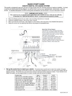
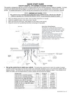
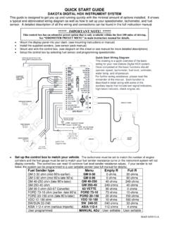
2 Self Diagnostic Easier Installation No Vacuum Required Smaller Module Single Unit Mounting Connectors with Positive Contact and Lock No Clutch Switch Needed (except Diesel) Additional Throttle Hardware Included in Kit Compatible with Neutral Safety Connections Improved Operation Closer, More Accurate Control of Set Speed Accurate Coast/Reduce Speed Tap-Up, 1 MPH per tap Tap-Down, 1 MPH per tap Controlled Resume Rate Here is an overview of the wiring diagram: Please Note: If you are using taillights please wire in a relay as shown on page 3 to allow for proper Cruise Control Operation . - 2 - 650014B Additional Notes: Wiring Information: The wire connections that you will need to make into your vehicle are as follows: RED: Connect to constant 12 volt source.
3 This should go to the fused terminal that feeds power to the brake lights. BROWN: Connect to switched 12 volt source. This should be connected to an accessory terminal of the fuse panel capable of supplying 10 amps. This wire should have 12 volts when the ignition key is in the accessory and run positions, but not in the off or start positions. BLACK: Connect to a good ground point on the chassis or fire wall. VIOLET: Connect to cold side of brake light switch. This wire should have 12 volts only when the brake is depressed. When the brake is not depressed it should be grounding through the brake light bulbs. If the brake light bulbs are not connected or are burned out, the system will not operate.
4 LED brake lights will not provide proper grounding. If you have LED brake lights, use a relay as shown on page 3. BLUE: Connect to negative side of ignition coil. On GM HEI ignitions or MSD ignitions connect to TACH terminal. Do not route the BLUE tach wire and GRAY speed wires along side each other. The tach wire can cause interference with the speed signal wire. GRAY: see following section on SPEED CONNECTION. Throttle connection: The Cruise Control installation manual provides detailed diagrams for connecting the servo to the throttle. These diagrams cover basic OEM factory throttle hook-ups. It may be necessary to use a slight variation of one of the diagrams with aftermarket carburetors.
5 Control switch: There are various types of turn signal and dash mount control switches that are available. The type of control switch that we supply with the cruise control is a closed circuit type for a turn signal handle control and open circuit for dash mount switches. If you will be connecting to a factory GM 4 wire control switch, they are open circuit type. GM switches which do not have 4 wires are not compatible with this cruise control. Ford cruise control switches are not compatible with this cruise control. SPEED CONNECTION: When using a cable drive speedometer, the metal, 8,000 pulse per mile, speed pulse generator is placed in line with the cable. This can be done at either the transmission side or the speedometer side of the cable.
6 The two wires from the sensor connect as follows: Systems with black and gray wires twisted together from the sensor: BLACK wire to ground, GRAY wire from sensor harness to GRAY wire from cruise harness. Systems with a gray cable with a red and black wire inside: BLACK wire to ground, RED wire from sensor harness to GRAY wire from cruise harness. When the cruise control is used with a Dakota digital STR3B, STR4B, STR5B, STR6B, STR3C, STR6C, STR5D, STR6D, STR2000 display system the gray wire should be connected to the SPEED terminal on the display system control box. On the VFD3, VFD3X or VHX display systems, the gray wire should be connected to the 2K or SPD OUT terminal, (2K or 4K PPM signal), on the display system control box (please see VFD3/VHX instruction manual for changing between 2K and 4K).
7 When the cruise control is being installed into a newer vehicle which does not use a speedometer cable consult the Vehicle Technical Information Guide supplied with the cruise. This will provide you with information on where to connect the gray wire. SETTING PROGRAMMING SWITCHES: Switch** 1 2 3 4 5 6 7 8 9 10 11 12 Application 1 ON ON ON ON *ON Application 2 ON ON ON *ON Application 3 ON ON ON ON ON *ON * SW 12 will be OFF for HND-2 applications ** all other switches to the OFF position Application 1: 8cyl, Auto tranny, STR series control box, closed circuit control switch, 8K PPM pulse generator Application 2: 8cyl, Auto tranny, VFD3, VFD3X or VHX control box (2K OUT/ SPD OUT), closed circuit control switch Application 3: 8cyl, Auto tranny, VDO 3-wire pulse generator, closed circuit control switch The description of the switch functions are found on page 6 of the Cruise manual.
8 If you experience a surging when the cruise control engages then turn switch number 1 off. TROUBLE SHOOTING: If the system fails to operate after making all of the proper connections, consult the self diagnostics procedure on page 16. The Diagnostics LED is located beside the programming switches, under the rubber plug on the actuator. In order for the cruise to regulate the speed properly, the car must be tested on the road and not with the tires elevated off the ground. - 3 - 650014B Please Note: If you are using taillights please wire a relay as shown here to allow for proper Cruise Control Operation . Use Dakota digital RLY-1, or any 5 pin SPDT normally open relay.
9 When using the relay, the Violet must go to Pin 30 (RLY-1 Black) ONLY. Pin 86 (RLY-1 Red) is the only wire that now goes to the cold side of the brake switch. TROUBLE SHOOTING: If the system fails to operate after making all of the proper connections, consult the self diagnostics procedure on page 16. The Diagnostics LED is located beside the programming switches, under the rubber plug on the actuator. In order for the cruise to regulate the speed properly under load, the car must be tested on the road and not with the tires elevated off the ground. - 4 - 650014B Dakota digital ELECTRIC CRUISE CONTROL UNIVERSAL APPLICATION, INSTALLATION, & OWNER S MANUAL CONTENTS: PARTS 4 PARTS 4 SAFETY PROCEDURES.
10 5 HELPFUL 5/6 SWITCH 6 INSTALLATION ..7 OPERATING INSTRUCTIONS ..20 The Dakota digital Cruise Control System Includes: Your vehicle must have a VSS (Vehicle Speed Signal) wire or an available signal generator for installation of the Cruise Control. The CRS-2000 includes the appropriate signal generator in the kit. Qty. Description 1- A 250-2316 CRUISE MODULE 1- B 250-2317 CRUISE HARNESS 1- C 250-3607 CRUISE CABLE 1- D 250-2236 MODULE BRACKET 1- E 250-3700 CABLE BRACKET 1 1- F 250-3425 CONVOLUTED TUBING (58 ) 1 1- 250-2214 HARDWARE PACKAGE (UNIVERSAL) 1- 250-2232 HARDWARE PACKAGE (-G, GM KIT) 2- G1 MODULE BOLT 2 2- G2 SELF-THREADING BOLT (M6 X 19) 4 1- G3 BEAD CHAIN 1 2- G4 BEAD CHAIN CONNECTOR 2- G5 CONNECTOR COVER 1- G6 LOOP CABLE (67MM) 1- G7 THREE BEAD CONNECTOR Qty.