Transcription of ePark Controller System PDS Jan2010 - EV West
1 Last revised: 26-Jan-2010 Author: Steve Reau BorgWarner Confidential Page 1 of 19 ePark Controller System PDS ECU System Product Definition Specification HEV ePark Controller Doc Number: ECU Program Engineering Manager Approved: Date: ECU Program Engineer Approved: Date: Preliminary As a preliminary document, information contained within this specification is FOR REFERENCE ONLY! This document is unchecked is to be used for internal BWA use only. Recipient is responsible for maintaining up to date copies of this document from the document author.
2 Release Number: Release Date: Last revised: 26-Jan-2010 Author: Steve Reau BorgWarner Confidential Page 2 of 19 ePark Controller System PDS TABLE OF CONTENTS 1 DOCUMENT 3 2 REFERENCE DOCUMENTS .. 3 3 DOCUMENT 3 4 System OVERVIEW .. 4 5 5 Vehicle Package 5 Electrical 5 Vehicle Networking 5 Tools 5 Diagnostics Support 5 6 ECU FUNCTIONAL DEFINITION .. 6 Module Park / Unpark 6 Park to UnPark Shift 6 Unpark to Park Shift 7 Thermal 7 Bus Signal 7 CAN Message 8 CAN message 10 Service Diagnostic Mode 15 In-Field Flashing 15 Power 15 7 ECU HARDWARE DEFINITION.
3 16 Electrical Block 16 Electrical 16 Environmental 17 Storage 17 Operating 17 ECU Mounting Location/ 17 Electrical 17 Vehicle Operating 17 Max Current 17 Parasitic 17 8 9 CALIBRATION ..18 10 CHANGE LOG ..18 Last revised: 26-Jan-2010 Author: Steve Reau BorgWarner Confidential Page 3 of 19 ePark Controller System PDS 1 Document Scope This document is intended to provide an overview definition of the ECU product and the System it is intended to control. 2 Reference Documents Document Name Version Source HEV CAN Database BW 3 Document Acronyms Acronym Description BW Borg Warner DMC Digital Motor Controller DTC Diagnostic Trouble Code ECU Electronic Control Unit ePark Electric Park HEV Hybrid Electric Vehicle IGN Ignition PMDC Permanent Magnet Direct Current TCM Transaxle Control Module Last revised: 26-Jan-2010 Author: Steve Reau BorgWarner Confidential Page 4 of 19 ePark Controller System PDS 4 System Overview The ePark Controller is part of the transmission park System .
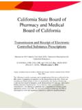
4 The ePark Controller is comprised of an ECU, a geared PMDC motor, non-contacting rotary position sensor, and a temperature sensor. The ePark Controller interfaces and receives information with other vehicle systems over a vehicle CAN bus. The ECU directly controls the ePark shift motor providing torque to the transmission park System that engages or dis-engages a parking pawl mechanism allowing the transmission/vehicle to move or not. Shifting into or out of park is only attempted if the System meets defined shift criteria and a request for a shift is made by the operator.
5 VehicleECU / ActuatorTransmission / ParkingPawlMotor RPMPark RequestKey SwitchTorqueParking PawlLocked / Unlocked Last revised: 26-Jan-2010 Author: Steve Reau BorgWarner Confidential Page 5 of 19 ePark Controller System PDS 5 Interfaces Vehicle Package Interface The ECU will have a mechanical design to allow ease of physical packaging onto a single speed transmission for electric vehicles. 2D drawings and 3D model data will be provided to allow development of packaging the ECU into the vehicle. Electrical Interface The ECU will be designed to allow the end customer connector the ePark System with a single connection.
6 The connection will be a single multi-cavity electrical connection. This connection shall provide the ECU with power, ground and serial communication. Vehicle Networking Interface The ECU will be designed to operate as a node on the Vehicle CAN bus infrastructure. It is expected that most of the Input data will come as CAN signal inputs to our System . The required signal inputs for the ECU to function are defined within this document. Tools Interface The ECU will be designed to allow Vector CAN tools interfacing to the System for vehicle development purposes.
7 Diagnostics Support Interface The ECU will be designed to provide diagnostic mode support features to allow for System debug, EOL testing and for after market serviceability. Last revised: 26-Jan-2010 Author: Steve Reau BorgWarner Confidential Page 6 of 19 ePark Controller System PDS 6 ECU Functional Definition Module Initialization When the power is turned on, as detected by the IGN line into the ECU reading greater than or equal to Vdc, the module will be ready to receive CAN messages within 120 ms and send out the first CAN message between 120-500ms.
8 All fault conditions will be re-diagnosed at ignition on and if a fault condition exists, the appropriate DTC will be considered active. The module will be ready to initiate the first shift request within seconds of ignition on providing all shift conditions are met. When the module powers up, it will receive park request - {0-off, 1-park, 2-unpark, 3-Invalid} from DMC through CAN, and respond with park, unpark, or no-action. Actual Motor Position Received CAN Request Shift Motor Response Park Park No Action Park UnPark Unpark Park Off No Action Unpark Park Park Unpark Unpark No Action Unpark Off No Action Unknown1 Park Park Unknown1 Unpark Unpark Unknown1 Off No Action Park / Unpark Shifting Shifts are only allowed when vehicle conditions specified are satisfied.
9 Once the motor starts moving the shift conditions are no longer checked. The shift conditions are: Park to UnPark Shift Criteria No general encoder fault No motor open/shorted ground fault No motor open/short to battery fault No thermal protection fault 1 Only at cycle IGN Last revised: 26-Jan-2010 Author: Steve Reau BorgWarner Confidential Page 7 of 19 ePark Controller System PDS Unpark to Park Shift Criteria No general encoder fault No motor open/shorted ground fault No motor open/short to battery fault ENGINE_RPM_LOW_LIMIT < electric motor speed < ENGINE_RPM_HIGH_LIMIT No thermal protection fault Once a shift is initiated, the shift to the requested destination will be completed.
10 Shift requests during a shift will be ignored until the current shift is completed. If, during a shift attempt, the destination is not detected in MOTOR_ON_TIME seconds, and there are no detected System faults, the shift motor will be considered stalled. If the shift motor is stalled, it will be stopped. A shift System timeout fault will be set as defined in DTC section The maximum amount of time the shift motor is energized is MOTOR_ON_TIME seconds. Thermal Management The ECU is equipped with a thermistor mounted to the PCB to determine the modules board temperature.
![BorgWarner eGearDrive(for customer) [兼容模式]](/cache/preview/a/d/d/9/8/4/2/5/thumb-add9842573e443c2740dc638242b6cd8.jpg)