Transcription of ES-CO2RM & ESCO2RMPP - CO2 Sensor - …
1 029 2085 840023. 07. 18. Leaflet Number 671537 The EMC Directive 2014/30/EUThe Low Voltage Directive2014/35/EUES-CO2RM & ES-CO2 RMPPCO2 Sensor installation and IntroductionThese are surface mounted room carbon dioxide (CO2) sensors which also incorporate a temperature Sensor . They are designed sense the room conditions for residential or commercial office buildings. They are designed to be compatible with Nuiare s Ecosmart range of fans and control system with simply plug and play : CO2 & temperature Sensor requires SELV power supply by : CO2 & temperature Sensor supplied with SELV ac power RatingsSensing ranges: 0-2000ppm CO2 and 0-50 : 0-10V dc proportional output, maximum load consumption: Typically 10mA plus pulses of for (every 15s).Warm up time: <5 : Mains supply to power pack must be 230V 1~ : SELV power supply (by others) must have output of 12 Vac (+/-5%) or 15-35V dc. Please note that proprietary 12 Vac transformer would only produce 12V at maximum load.
2 Due to the low current absorbed by the Sensor ; these would be running at very high output voltage (typically >30 Vac) and are therefore not suitable. If in doubt use the ES-CO2 RMPP to ensure InstallationInstalled environment: 0-50 C and up to 90% RH installation must be carried out by competent personnel in accordance with all local and national statutory regulation; IEE, HVCA unit must be installed indoors, away from direct source of heat ( radiator, direct sunlight), any water spray or steam generating mounting surface must be free from vibrations. Do not install the Sensor in environment containing high level of contaminants; dust; corrosive gases; commercial kitchens. Install the Sensor at approximately head height or slightly higher for best response a small screwdriver to push in the clip at the bottom of casing to open the front cover. Remove the top half and store it in a safe place. Use the base of unit as a template to mark the fixing positions.
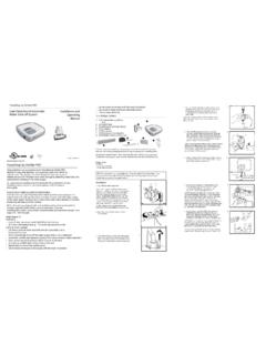
3 Drill and insert appropriate fasteners into the holes. Feed the cable from the SELV side of power pack and the Ecosmart data cable through the large hole of the base and connect these to the Sensor . Mount the base of the unit and replace the front a small screwdriver to push in the clip at the bottom of casing to open the front cover. Use the base of unit as a template to mark the fixing Dimensions (mm)Width 85, Height 100, Depth 26 Cable from 1. Removing cover & mounting 029 2085 840023. 07. 18. Leaflet Number 671537 installation and MaintenanceES-CO2RM & ES-CO2 RMPP - CO2 WiringWire the cables from the power pack into the terminal block as per wiring diagram below. Plug the Ecosmart data cable into the socket on the PCB before refitting the top half of the Sensor back on the base. The other end of the data cable must be connected to the : do not connect any other devices to the power supply. The lower and upper threshold values can be adjusted as shown in the following tables below and Temperature Threshold - Switches 1 to 36 5 4 3 2 1 GNDCO2 TNCGNDSELV 12V ac +/-5%from power supply (by others)+V6 5 4 3 2 1 GNDCO2 TNCGNDSELV +15V TO +35V dcfrom power supply 0V(by others)+V6 5 4 3 2 1 PSU3 pin plug.
4 Connect to a suitable230V 1-50Hz socketGNDCO2 TNCGND+VFigure 2. ES-CO2RM wiring to AC power 3. ES-CO2RM wiring to a SELV DC power 4. ES-CO2 RMPP wiring to 5. CO2 threshold Data Cable InstallationA 4-core SELV data cable is used to connect devices such as sensors to the fan and for inter connecting multiple fan not run data cable in the same conduit as the mains cables and ensure there is a 50mm separation between the data cable and other cables. The maximum cable run between any two devices is 300m when it is installed in accordance with the note that the total data cable length used in any system must be less than 1000m. Keep the number of cable joints to a minimum to ensure the best data transmission efficiency between OperationThe Sensor will monitor the carbon dioxide (CO2) and temperature (see note 1) within the room. If either reading reaches the low threshold values ( C1 & T1) in fig. 5 then a signal will be sent to start running the fan at minimum speed.
5 As the room CO2 and temperature rises, the fan speed will progressively increase in steps until the upper threshold values are reached. When both CO2 and temperature readings are in operation, whichever reading that results in higher fan speed will be used by the fan unit. The threshold values and other operations can be adjusted by setting DIL switches on the PCB to different 1: As supplied; the default operation of the Sensor will be based on carbon dioxide reading. If operation with both carbon dioxide and temperature is desirable then change position of switch 7 to ON .Note 2: Use switch 8 to change the off state (see fig. 5 below).Max speedMinspeedSee or C1 note 2T2 or C2 CO2 orsignalTemperatureLower AdjustablethresholdUpper AdjustablethresholdSwitch SettingsThreshold Temperatures (see note 1)123T1 ( C)T2 ( C) 029 2085 840023. 07. 18. Leaflet Number 671537 installation and MaintenanceES-CO2RM & ES-CO2 RMPP - CO2 CO2 Threshold - Switches 4 to 6 Switch SettingsThreshold CO2 Values (see note 2)456C1 (ppm)C2 (ppm)OffOffOff10001500 OnOffOff9501500 OffOnOff9001500 OnOnOff8501500 OffOffOn10001750 OnOffOn9501750 OffOnOn9001750 OnOnOn8501750 Switch number 7 switch to On position to enable the Sensor to operate with both CO2 and temperature reading.
6 Switch number 8 switch to On position to run the fan at minimum speed even if the readings are below the lower threshold. Please note there must be an enable signal present in order for the fan to run; from a switched live, ES-PIR ONONSW1 1 2 3 4 5 6 7 8 Data cable 6. PCB switch MaintenanceThis unit does not require any routine maintenance. However, it is advisable to check the condition of the circuit board and wiring to ensure it has not been damaged by the installed conditions; unforeseen condensation etc. Remove any accumulated dust with a soft WarrantyThe 5 year warranty starts from the date of delivery and includes parts and labour for the first year. The labour element is subject to full, free and safe access to the equipment as recommended by the CDM regulations. The remaining 4 years covers replacement parts warranty is void if the equipment is modified without authorisation, is incorrectly applied, misused, disassembled, or not installed, commissioned and maintained in accordance with the details contained in this manual and general good practice.
7 The product warranty applies to the UK mainland and in accordance with Clause 14 of our Conditions of Sale. Customers purchasing from outside of the UK should contact Nuaire International Sales office for further After Sales EnquiriesFor technical assistance or further product information, including spare parts and replacement components, please contact the After Sales 02920 858 400