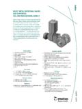
Transcription of ESD VALVE SELECTION GUIDE GENERAL ESD VALVE …
1 ESD VALVE SELECTION GUIDE . GENERAL ESD VALVE DEFINITION. ESD/ESV valves are the final defence against proc- ess misreactions. These valves have a function which requires much more reliable performance than standard remotely operated on-off valves . Still today ESD valves are ranked often as ordinary shut-off valves in specifications. valves as such may still remain the same but being a part of Safety Instrumented Function (SIF) the performance expectations are much higher. There must be a prove for a reliable long term performance. MTBF. (Mean Time Between Failure) number needs to be given to Safety calculations (SIL).
2 ESD / ESV valves are in modern systems con- nected to Programmable Locig Controller (PLC) This is the most critical situation for valves . Unless and are together with sensors forming a Safety the VALVE is not frequently tested there is no guar- Loop. Whenever sensors identity an upnormal dan- antee that it is available and does the desired gerous process situation PLC disconnects the safety function. This can cause a major catastro- power to ESD VALVE solenoid and the VALVE goes to phe. desired fail safe mode by means of spring force (fail close or fail open). 1.
3 STANDARDS 6. MATERIALS. - IEC 61508 - coatings - IEC 61511 - NACE materials - DIN 19250. - ISA 7. FIRE PROTECTION. - application standards ( furnace). 8. SAFETY INTEGRITY LEVEL (SIL). 2. SPECIFICATIONS - MTBF, DC, PFD, SIL. - how to identify ESD VALVE - process duty description 9. TOTAL LIFE CYCLE. - tag number 10 ESD 20 EN Issue 10/2005. 10. APPLICATIONS. 3. valves . - SELECTION process 11. QUALITY PACKAGE. - typical valves - std. Q-plans - testing procedures 4. ACTUATORS - NDE options - SELECTION process - torque output / safety margins 12. TERMINOLOGY. 5. ACCESSORIES.
4 - Neles ValvGuard - typical ESD connection diagrams M E T S O AU TO M AT I O N. 1. STANDARDS. MIL. DIN -> IEC 61508. ISA IEC 61508 is a globally recognised new safety standard specific to process industry. Very strong guidelines are given there to process operators to test and prove the availability and functional safety of the safety loop including the final elements and ESD valves . This standard gives practical tools for Safety Design process. As well it is a tool for Auditors to review plants Safety efforts. Very typically Insurance companies would utilize this standard to review if all Safety measures are taken.
5 This can have a great impact to Insurance fees being either lowered or increased. Compliance to IEC 61508. Part 1 of the IEC 61508 demands certain documentation requirements for the development of safety critical devices. As basis documents, the SRS (Safety Requirements Specification) and the V&V Plan (Validation and Verification Plan) were prepared. For the specific requirements of part 2 (system architecture, safe failure fraction, diagnostic, measures against systematic faults and measures to avoid failures during design and development) and part 3 (software), the finally selected measures meet the requirements of SIL 3.
6 Regarding the control of failures, the following results were estimated: 1. Hardware fault tolerance is 0. 2. Safe failure fraction of the pneumatic part is > 90 % (low complex component). 3. Safe failure fraction of the electronic part: No hardware/software fault could lead to a dangerous failure in case of a demand. From this point of view the Neles ValvGuard system could be used up to and including SIL 3. For the PFD calculation the final VALVE is dominant for the result. The diagnostic coverage of a final VALVE could be between 75. % and > 90 % depending on the type of VALVE .
7 The failure rate, safe failure fraction resp. diagnostic coverage of the final VALVE and the automatic test time interval have to be used for the PFD calculation. Depending on this calculation and the required hardware fault tolerance of the application (some applications require a hard- ware fault tolerance of 1) the max. SIL level is defined. If the PFD calculation does not reach SIL 3 and/or a hardware fault tol- erance of 1 is required, a dual redundant configuration has to be used as described in the ValvGuard safety manual. 2. SPECIFICATIONS. How to identify an ESD VALVE ESD valves are part of Safety System.
8 The function can be clearly specified in the specification. Quite often specification requires certain safety margins for actuator sizing. Some of above mentioned Safety related standards can be mentioned. Duty description Data sheets describe the VALVE to be an ESD / ESV or Emergency VALVE . Tag number is XV or XCV or ZV. Jammer or latching devices are specified Volume tanks are specified for emergency function three strokes in cause of supply air failure Strict operating times are specified Strict safety margins in actuator sizing is requested -2- E S D VA LV E S E L E C T I O N G U I D E.
9 3. valves . VALVE series to be considered ball valves 150 lbs 1" 8" X-serie, floating, FB or RB, Bulletin 1X20, 1X21. 150 lbs 08" 16" X-serie, trunnion, FB or RB, Bulletin 1X22. 300 lbs 1" 6" X-serie, floating, FB or RB, Bulletin 1X20, 1X21. 300 lbs 02" 16" X-serie, trunnion, FB or RB, Bulletin 1X22. 150/300/600 lbs 02" 36" D-serie, trunnion, FB or RB, Bulletin 1D20. Alternative series Top 5 (1,5" 16"), Bulletin 1T520. Soft seated alternative see bulletins; 1X24 and 1X25. Butterfly valves 150/300 lbs, wafer/lug 3"- 16" LW/LG series, Bulletin 2LW20. 150/300 lbs, wafer/lug 18"- 48" L1C/L1D series, Bulletin 2L121.
10 150 600 lbs, flanged 4" 64" L6 series, Bulletin 2L621. Soft seated alternative Wafer-Sphere (3" 60"), Bulletin 2WS21, 2WS22. SELECTION process Application type Emergency closing or venting, note if selected VALVE is capable for partial stroke testing (eg. venting vs. but- tefly). Pressure Shut-off pressure, operating pressure, see temperature relation tables, remember shaft strenght Temperature Soft parts, body material, coatings, seat construction bearings, high temp. extension, low Fluid Corrosive, solids, toxic, explosive (O2). Viscosity, errosion, corrosion, solidifying, coke build-up Materials CF8M, WCB, LCC, C5, note temperature, chemical resistancy, NACE.

