Transcription of ESD5500E Series Speed Control Unit - governors …
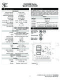
1 1 ESD5500E SeriesSpeed Control unit 2016 Copyright All Rights ReservedESD5500E Series Speed Control unit PIB 1002 E21 INTRODUCTIONSPECIFICATIONSPERFORMANCEI sochronous Operation or betterSpeed Range / Governor1 - KHz ContinuousSpeed Drift with Temperature 1% MaximumIdle Adjust CW60% of Set SpeedIdle Adjust CCWLess than 1200 HzDroop Range1 - 5% regulationDroop Adj. Max. (K-L Jumpered)400 Hz., 75 Hz per A changeDroop Adj. Min. (K-L Jumpered)15 Hz., 75 Hz per A changeSpeed Trim Range 200 HzRemote Variable Speed Range500 - KHzTerminal Sensitivity J L N P100 Hz.
2 , 15 Hz/Volt @ K Impedance735 Hz., 60 Hz/Volt @ 65 K Impedance148 Hz., 10 Hz/Volt @ 1 Meg Impedance10 VDC Supply @ 20 mA MaxINPUT / OUTPUTDC Supply12-24 VDC Battery Systems Transient and Reverse Voltage ProtectedPolarityNegative Ground (Case Isolated)Power Consumption50mA continuous plus actuator currentSpeed Signal RangeSpeed Sensor - 120 Volts RMSA ctuator Current Range@ 77 F (25 C)Min. AMax. 10 ARELIABILITYV ibration1G @ 20-100 HzTesting100% Functionally TestedENVIRONMENTALA mbient Temperature-40 to 85 C (-40 to 180 F)Relative Humidityup to 95%All Surface FinishesFungus Proof and Corrosion ResistantCOMPLIANCE / STANDARDSA gencyCE (EN55011, EN50081-2, EN50082-2), RoHS, Lloyds Register, DNV/GL, Bureau Veritas PHYSICALD imensionSee Wiring Diagram and lb.
3 ( kg)MountingAny position, Vertical PreferredThe ESD5500E Series are all-electronic devices designed to Control engine Speed quickly and precisely in response to transient load changes. The ES-D5500E will Control a wide variety of engines in an isochronous or droop mode when connected to a proportional electric actuator and magnetic Speed sensor. The ruggedly built ESD5500E is designed to withstand the engine environment. Light-Force variations are in a cabinet, engine enclosure, or sealed metal orientation allows fl uids to drain in moist Extreme Heat3 INSTALLATION & OUTLINE DIAGRAMPROD.
4 UnitESD5520 ELight Force: Optimized For Lower Current ActuatorsESD5522 ELight Force / EFC Forward Acting / Enhanced Droop / Smoke LimitingESD5526 EFor Use With T1 & T2 ATB Gas Applications / Anti WindupESD5528 EFor Use With T3 & T4 ATB Gas Applications / Anti WindupMODELSin(mm)2 2016 Copyright All Rights ReservedESD5500E Series Speed Control unit PIB1002 E6 START THE ENGINEThe Speed Control unit governed Speed setting is factory set at approximately engine idle Speed . (1000 Hz., Speed sensor signal or 600 RPM) If the engine does not start, adjustment of the Speed potentiometer may be the engine with DC power applied to the governor system.
5 The actuator will energize to the maximum fuel position until the engine starts. The governor system should Control the engine at a low idle Speed . If the engine is unstable after starting, refer to Section 8 ADJUSTING FOR Speed SETTINGRECOMMENDATIONS1. Shielded cable should be used for all external connections to the ESD One end of each shield, including the Speed sensor shield, should be grounded to a single point on the ESD BEFORE ENGINE STARTUPMake sure the following adjustments are set before starting the PositionSTABILITYM iddle PositionSPEED TRIM CONTROLM iddle PositionSTARTING FUELFull CW (Maximum Fuel) Speed RAMPINGFull CCW (Fastest)The governed Speed set point is increased by clockwise rotation of the Speed adjustment Control .
6 Remote Speed adjustment can be obtained withan optional 5K Speed Trim Control . 8 ADJUSTING FOR STABILITY Once the engine is running at operating Speed and at no load, the following governor performance adjustments can be made to increase engine TIMECOMPENSATIONJUMPERSTABILITY the GAIN adjustment clockwise until instability , gradually move the adjustment counterclock-wise until stability , move the adjustment one division further counterclockwise to insure stable performance (270 potentiometer). If instability persists, adjust the next STABILITY1.
7 Follow the same adjustment procedure, steps 1 - 3, as the GAIN , adjustments made at no load achieve satisfactory performance. If further performance improvements are required, refer to Section (12) SYSTEM TROUBLESHOOTING. NOTETERMINALDEFINITIONNOTESA & BActuator (+/-)#16 AWG ( sq) or larger wireC & DMagnetic Speed Pickup (D is ground)Wires must be twisted and/or shielded for their entire lengthGap between Speed sensor and gear teeth should not be smaller than in. (.51mm) Speed sensor voltage needs to be at least 1V AC RMS during crankE & FBattery Power (-/+)#16 AWG ( sq) or larger wireA 15 amp fuse must be installed in thePositive battery lead to protect against reverse voltageBattery positive (+) input is Terminal FGGround SignalHNOTE: In Certain Cases, A Jumper Be-tween Terminals H & G Can Be Added for 12V Systems with Actuator Currents Above 5 AJVariable Speed5K Resistive Nominal.
8 See Section10 Table 1K & LDroop SelectActive When ClosedMIdle SelectClose for IdleNAccessory InputLoad Sharing/Synchronizing, 0-10 VDC (5V Nominal, Reversed, 148 Hz/Volt) PAccessory Power Supply10 Volt Output To Power GAC Load Sharing and Synchronizing Modules4 WIRINGCW*SEE SPECIFIC ACTUATOR PUBLICATION FOR PROPERWIRING OF ACTUATOR BASED ON BATTERY VOLTAGE*OPTIONAL ACTUATORCABLE SHIELDING TOMEET CE DIRECTIVEGROUND TO CASEGROUND TO CASEABCDEFGHJLMNPACTUATORPICK-UPBATTERYA UX10 VOUTPUTBATTERY_+S1 FUSE15A MAXGROUND REFERENCEADD JUMPER FOR 12 VBATTERY OR ACTUATORCURRENTS ABOVE 5 ASPEED TRIMCONTROL - 5 KKCLOSE FOR DROOPCLOSE FOR IDLEACTUATORMAGNETICPICK-UPDROOPIDLE- +ACCESSORY POWERSUPPLYACCESSORY
9 INPUTDROOPDROOPIDLESPEEDPEEDAMPINGIMPORT ANT: Speed Adjustment Is a 25 Turn Potentiometer 3 2016 Copyright All Rights ReservedESD5500E Series Speed Control unit PIB1002 E 11 ADDITIONAL FEATURES & OPTIONAL WIRINGIDLE Speed SETTINGIf the IDLE Speed setting was not adjusted as detailed in Section 9 Starting Fuel Adjustment , then place the optional external selector switch in the IDLE position. The idle Speed set point is increased by the clockwise rotation of the IDLE adjust-ment Control . When the engine is at idle Speed , the Speed Control unit applies droop to the governor system to insure stable : If not using the idle method, you can lower idle to the bare minimum (even if it s not being used) for smoke CIRCUIT & SOFT COUPLINGS witch 1(C1) controls the Lead Circuit.
10 The normal position is ON. Move the switch to the OFF position if there is fast instability in the system. Switch 2(C2) controls a circuit designed to eliminate fast erratic governor behavior, caused by very soft or worn couplings in the drive train between the engine and generator. The normal position is OFF. Move to the ON position if fast erratic engine behavior due to a soft coupling is experiencedDROOPIDLESPEEDC1 OFFONLEAD CIRCUITOFFONC2 SOFT COUPLINGACCESSORY INPUTThe Auxiliary Terminal N accepts input signals from load sharing units, auto synchronizers, and other governor system accessories, GAC accessories are directly connected to this terminal.